Item | Specifications | |
AC | Input voltage (VAC) | AC 3PH 380V (-15%)–440V (+10%) Rated voltage: 380V |
| AC 3PH 520V (-15%)–690V (+10%) Rated voltage: 660V | ||
Input frequency (Hz) | 50Hz or 60Hz; allowed range: 47–63Hz | |
Efficiency | >97% | |
DC | Input voltage (VDC) | 380VAC voltage class: 500V (+35%/-30%) |
| 660VAC voltage class: 850V (+35%/-30%) | ||
Output | Output voltage (V) | Voltage open loop mode (with sine filter): 380/500/660V±3%, configurable. If the set value is higher than the input voltage, a transformer is required. |
| Voltage closed loop mode (with sine filter): 380/500/660V±1%, configurable. If the set value is higher than the input voltage, a transformer is required. | ||
Output frequency (Hz) | 0–400Hz, frequency adjustable; fluctuation range: -0.5%–+0.5%. | |
Output voltage distortion | With sine filter: Linear load <5%, load power factor (PF) ≥ 0.8 | |
Dynamic response | -10% IEC62040-3 CLASS 1–+10% IEC62040-3 CLASS 1 | |
Control | Motor control mode | V/F control, sensorless vector control (SVC) mode |
Motor | Motor type: Asynchronous motor (AM) and synchronous motor (SM) | |
| Voltage: 0–U1 (motor rated voltage), 3PH symmetrical, Umax (VFD rated voltage) at the field-weakening point | ||
| Short-circuit protection: The motor output short-circuit protection meets the requirements of IEC 61800-5-1. | ||
| Frequency: 0–599Hz; frequency resolution: 0.01Hz | ||
| Carrier frequency: 1kHz–15kHz. Refer to the function code P00.14 for the default carrier frequency. | ||
| Maximum motor cable length: 50m | ||
Voltage control method | Open-loop voltage, closed-loop voltage | |
Phase compensation mode | Manual phase compensation mode, automatic phase compensation mode | |
Voltage reference method | PID control, Modbus communication, keypad | |
Frequency reference method | PID control, Modbus communication, analog input, keypad | |
Overload capacity | 150% overload for 1 minute | |
Automatic VFD fault reset | Supports automatic fault reset, with configurable reset attempts and reset interval time. | |
Undervoltage forced start function | When the battery bank has insufficient charge (for 380V systems: second undervoltage threshold configurable between 300–400V; for 660V systems: second undervoltage threshold configurable between 450–570V), if the VFD is still required to operate normally, its output voltage capability will be determined by the external transformer while maintaining full current output capacity without derating. Under these conditions, the system will suppress undervoltage fault alarms. | |
Peripheral interface | Analog input | 2 inputs; AI1: 0–10V/0–20mA; AI2: -10–+10V |
Analog output | One output; AO1: 0–10V/0–20mA | |
Digital input | Four regular inputs; max. frequency: 1kHz | |
| Two high-speed inputs; max. frequency: 50kHz; supporting quadrature encoder input; with speed measurement function | ||
Digital output | One Y terminal open collector output | |
| One high-speed pulse output; max. frequency: 50kHz | ||
Relay output | Two programmable relay outputs | |
| RO1A: NO; RO1B: NC; RO1C: common | ||
| RO2A: NO; RO2B: NC; RO2C: common | ||
Expansion interfaces | SLOT1, SLOT2, and SLOT3 (only on control boards of 7.5kW and higher VFD models); supporting programmable expansion cards, communication cards, I/O cards, grid synchronization cards, and more. | |
STO input | Two redundant inputs | |
Protection functions | Fault protection | More than 30 protection functions, such as protection against overcurrent, overvoltage, undervoltage, overtemperature, input phase loss, output phase loss, and overload. |
Bus undervoltage protection | DC bus undervoltage (first undervoltage threshold), supporting undervoltage pre-alarm output (relay output), and supporting second undervoltage threshold protection. | |
Input phase detection protection | Grid synchronization card detects signals: Input phase loss (UIPL), input reverse sequence (UIPE) | |
Output phase detection protection | Grid synchronization card detects signals: Output phase loss (UOPL), output reverse sequence (UOPE) | |
Phase lock fault protection | Voltage feedback and grid power phase lock failure (PLLE) | |
Other | Mounting method | Supports wall mounting, floor mounting, and flange mounting. |
Temperature of running environment | -10°C–+50°C. Derating is required when the ambient temperature exceeds 40°C. | |
Ingress protection (IP) rating | IP20 | |
Pollution degree | Degree 2 | |
Cooling method | Forced air cooling | |
Sine filter | A sine wave filter (optional accessory) is available to ensure compliance with lighting load requirements. | |
Popular Searches:

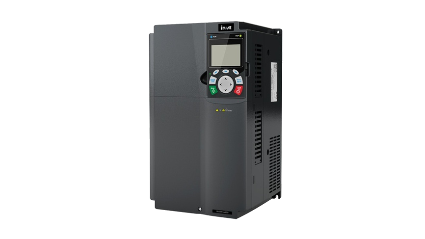
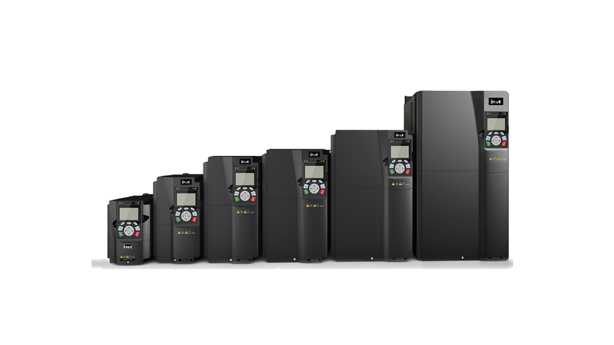
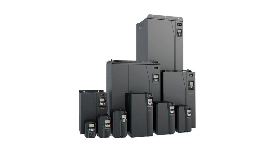
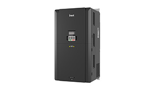
GD350-EP Series Dedicated VFD
The GD350-EP series Variable Frequency Drive (VFD) is custom-developed based on the GD350 hardware platform. It is applicable in industries such as shaft generator, shore power supply, emergency power backup, soft motor starting, power/variable frequency switching, and constant-voltage, constant-frequency (CVCF) power supply. It can be optionally equipped with a grid synchronization card, enabling quick synchronization and phase-locking between the grid power and backup power output.
·1.5~500kW
·380~690V
·Certified to CE, EAC, and other standards


 Images
Overview
Features
Specifications
Downloads
More Resources
Case
Videos
More
Features

Stable voltage and frequency output, no interference with other devices
 Employs closed-loop feedback control for output voltage regulation to ensure power stability. It comes standard with ferrite cores and offers optional filters to effectively prevent electromagnetic interference with other equipment.
01
Parallel operation with synchronization and phase-locking
Grid power synchronization terminal card tracks the input voltage to keep the output voltage synchronized with the grid. The VFD input power phase sequence (positive/negative) can be viewed through function codes.02
Reduced inrush current
The VFD can quickly switch to the backup power supply in the event of a grid power interruption or fluctuation. With inrush current maintained below rated current levels, it ensures continuous operation of critical equipment, thereby substantially improving overall power supply reliability.03
Enhanced safety
In applications with high safety requirements, such as fire safety systems and subways, GD350-EP's stable power supply ensures normal operation of critical equipment during emergencies, thereby enhancing overall safety.04
Specifications
Have questions or need support?
Our professional team is here to help.


Inquiry
TOP
Popular Searches:
Repair Progress Tracking | Identity Verification
To protect your repair information, please verify using the mobile number reserved on the service order.
Verify with the reserved mobile number
Verify
SMS Verification Code *
If you cannot receive the code, please contact the after-sales hotline. 400-700-9997


Contact INVT
Get in touch with INVT. Our team will get back to you shortly.
Full Name *
Company Name *
Email Address *
Phone Number *
Country *
City
Inquiry Type *
Product Category *
Select the product you're interested in.
-
Industrial Automation
-
Network Power
-
PV & ESS
-
e-Mobility
Your Message / Requirements *
I have read and agree to INVT Privacy Policy and Terms of Use
Captcha *