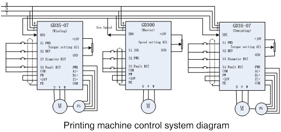
Abstract: The invention of printing machine is a sign of the improvement of human automation technology. It not only liberates human hands, reduces the workload, but also greatly improves the printing quality and efficiency. It is one of the essential automation equipment at present. Taking the printing machine system of a mechanical factory as an example, this paper introduces in detail the system solution of INVT GD35-07 series drive on printing machine.
Keywords: Gooddrive35-07, Printing machine, Open loop tension torque control, Coil diameter calculation
1. Introduction
With the development of power electronic technology, machine tool technology and information technology, the level of human automation technology is gradually improved. The invention and application of printing press is a best example.
Printing process belongs to the flow production operation, and the whole printing process includes two motion chains: press and paper feeding. This requires the printing machinery and equipment to be able to reasonably control the paper feeding motion chain and the printing press motion chain, so as to ensure that the printing materials can move according to the requirements and complete various printing operations in the process of printing materials.
Variable frequency inverter is a popular control device in printing machine in recent years. It uses frequency conversion technology and microelectronics technology to adjust the frequency and voltage of motor power supply. The rapid development of mechatronics technology and the maturity of inverter technology will further promote the application of inverter in printing and processing industry.
2. Control requirements
This paper takes a mechanical factory as an example. The site printing machine system needs to control three motors: two nos 2.2kW asynchronous motors (for main machine and unwinding) and one 1.5KW asynchronous motor (for winding). And the inverter configuration is as below:
| Application | Motor rating | Qty | Drive |
| Main motor | 2.2kW | 1 | GD300-004G-4 |
| Winding | 1.5kW | 1 | GD35-07-004G-4-C1 |
| Unwinding | 2.2kW | 1 | GD35-07-004G-4-C1 |
The requirements for inverter are as follows:
a) The paper tension should be stable in the whole equipment operation, and the tension can be adjusted by external potentiometer.
b) Three motors are master-slave control speed synchronization; the speed is given by the master.
c) At zero speed, the motor should be stable and not shake.
d) The communication performance should be good anti-interference performance.
3. Introduction of Goodrive35-07 inverter
Goodrive35-07 inverters special for tension control focus on the textile industry, printing and packaging industry, plastic machinery industry, paper industry, cable manufacturing industry. It has the function of tension control and coil diameter calculation and meets the requirements of medium and high-end winding applications.
In the algorithm, the tension control module is special for the tension control of winding/unwinding and the comprehensive solutions of the whole processing segments.
Use Goodrive35-07 tension control special inverter can replace torque motor, dc motor, such as tension controller and independently constitute a tension control system, and compared with traditional tension controller and frequency converter control scheme, the use of the frequency converter can make the system more concise, reduce cost, easy to maintain and gain more stable control effect.
4. System diagram and commissioning

4.1 System commissioning
Step 1: Motor autotuning, it is better to perform rotating autotuning for parameters identification;
(1) Set P00.18=1, restore to the factory setting
(2) Set P00.03 and P00.04 and P02 group
(3) Motor autotuning
a) Set P00.15=1, perform rotating autotuning
b) Set P00.15=2, perform static autotuning
If the motor can be de-coupled from the load, it is necessary to perform rotating autotuning; otherwise perform static autotuning, and the parameters after autotuning are saved in P02 group.
Step 2: Asynchronous motor close loop (encoder fitted on motor)
(1) Check the installation and parameters setting of the encoder
Set P20.01, P00.00=2, P00.10=20Hz and start the inverter. The frequency is 20Hz and observes the tested value of P18.00, if the value is negative, the direction of the encoder is reversed and set P20.02=1. If the tested value is large, the setting of P20.01 is wrong.
Observe P18.02 is fluctuated or not (counting value of Z pulse). If it fluctuates, there is interference to the encoder or the setting of P20.01 is wrong, check the wiring and shield layer.
(2) Close loop vector operation
Set P00.00=3 and begin close loop vector control, adjust P00.10, P03 group and PI parameters to stabilize the operation.
(3) Weakening control
Set P03.26=0~2000 and observe the control performance. P03.22~P03.24 can be adjusted according to the actual situation.
Step 3: Open-loop tension torque control mode
(1) Set basic parameters of production control such as the linear speed, tension reference, gear ratio and diameter of blank coil and cancel out the zero voltage through setting the lower limit of analog input in P05 group;
(2) Set the upper frequency of torque control and max output frequency
Set P26.02=0, P26.03=100.0% and observe the frequency value displayed by P19.05. Take this value as the max output frequency P00.03, upper limit frequency P00.04 and as torque control forward rotation, reverse upper limit frequency value P03.16, P03.17, then modify P26.02 as actual channel source.
(3) Select the counting mode of coil diameter: P26.13=1 (Calculation method of linear speed)
(4) Check the tension and the compensation torque
1) Identify the fixed moment of inertia of mechanical system
When no materials, if set P27.13 = 1, the keypad will display “-GuA-”. After press the operation key, the motor will runs and when the keypad display ”-End-”, the identification is finished. The identified inertia will be saved in P27.15.
2) Set the torque compensation coefficient of mechanical friction
Set p27.13 = 2, the automatic identification of mechanical friction torque will be completed.
3) Set the materials tension and adjust the torque compensation coefficient of mechanical friction
Set P26.00=2 when there are materials on the coil, on the basis of friction compensation coefficient, adjust the materials tension, static friction compensation coefficient, sliding friction compensation coefficient and high speed torque compensation coefficient and so on.
And ensure following parameters when blank coil:
a). Ensure the tension reference after stopping when the linear speed is zero. If the required tension is smaller, then increasing P27.05 which is only valid below P27.06, if it is bigger than P27.06, then it will become to 0 gradually;
b). Adjust the static friction compensation coefficient at some frequency which is below the threshold;
c). Accelerate gradually, make the running frequency is between the threshold value and 1/4 of the upper limit and then adjust the sliding friction compensation coefficient;
d). Adjust the high speed torque compensation coefficient at some frequency which is between 1/2 of the upper limit and the upper limit. After that, the parameter adjusting is finished and then decelerates. Observe the materials, and reduce the sliding friction compensation coefficient and high speed torque compensation coefficient; generally the compensation coefficient is less than or equal to the basic torque which is set through the tension value (observe through P19.19);
e). Set the linear speed to close to the Max. value, start the machine directly and observe whether there are materials loose during ACC and materials pressing during DEC. If yes, add the rotating inertia compensation, and if not, the parameters setting are finished
4) Inertia compensation commissioning
a). Ensure mechanic system inertia recognition has been done under empty coil. The recognized value is saved in P27.15;
b). Set P27.16, P27.17 to an estimated value.
c). Set P27.19, which is used to limit the torque upper limit value of rotation inertia compensation.
Note:
1. The master sends the synchronous speed signal to the slave in real time to realize the master-slave control of speed synchronization. The slave machine also uses the winding macro to control the open-loop tension torque, so as to ensure the constant paper tension during the operation.
2. The commands for master like running, stopping, speed, tension setting are given by the potentiometer and buttons on the control panel.
3. In order to prevent misoperation, the coil diameter reset function is only effective in the shutdown state.
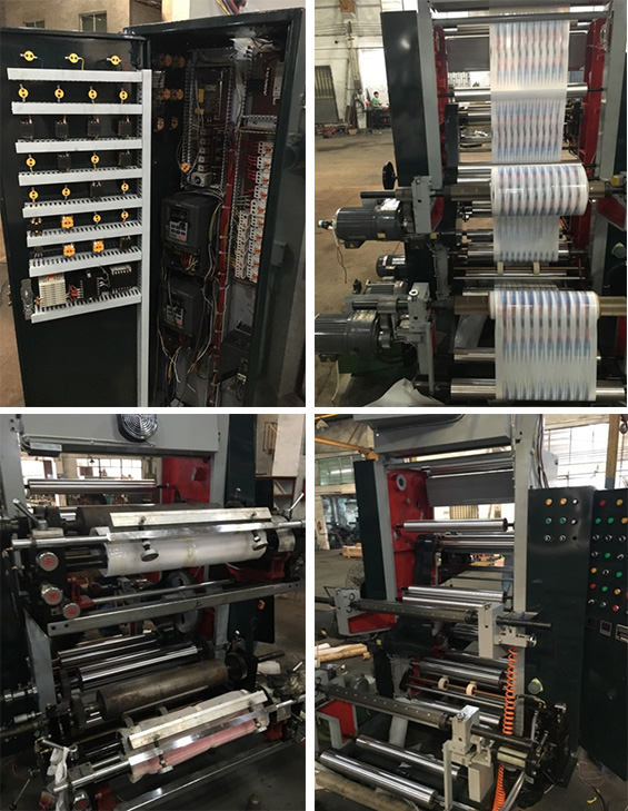
The panel and machine photos are as below:

4.2 Parameters setting for inverters
Table 1: GD35-07 Winding inverter

Table 2: GD35-07 Unwinding inverter

Table 3: GD300 Drive (Master)

The inverter used for this system has the functions of short circuit, overload, over-voltage, phase loss, stall and other protection and fault output functions, which can effectively ensure the safe and efficient operation of the system.
5. Conclusion
The excellent characteristics of the inverter provide more excellent conditions for the printing quality of the printing press, such as over-current, over-voltage, overload and other aspects of protection, which can significantly improve the efficiency and performance of the printing press. The successful application of GD35-07 series tension control special inverter in several printing machine systems has provided the foundation for the promotion of our products and solutions in this industry.
Reference
[1] 《Goodrive 35 Series Close Loop Vector Control Inverter》Shenzhen INVT Electric Co., Ltd
[2] 《Goodrive 35-07 Inverter Special for Tension Control》Shenzhen INVT Electric Co., Ltd


Our site uses cookies to provide you with a better onsite experience. By continuing to browse the site you are agreeing to our use of cookies in accordance with our Cookie Policy.