
| Item | Specifications | ||
| Input | Input voltage (V) | S2: AC 1PH 200V–240V; rated voltage: 220V 2: AC 3PH 200V–240V; rated voltage: 220V 4: AC 3PH 380V–480V; rated voltage: 380V 5: AC 3PH 500V–575V, rated voltage: 525V 6: AC 3PH 520V–690V, rated voltage: 660V Note: The fluctuation of (-15%) to (+10%) is an instantaneous value. | |
| Input frequency (Hz) | 50Hz or 60Hz; allowed range: 47–63Hz, with a maximum change rate of 20%/s | ||
| Short-circuit capacity | According to IEC 61439‑1, the rated short-time withstand current at the incoming terminals of the switchgear assembly is up to 100kA. The VFD is suitable for applications where the prospective short-circuit current does not exceed the breaking capacity (for example, 100kA) of its protective devices, and its rated operational current is significantly lower than this value—typically ≤ 1kA. | ||
| Output | Output voltage (V) | 0–input voltage | |
| Output frequency (Hz) | 0~599Hz | ||
| Control performance | Control mode | V/F control mode (space voltage vector control), sensorless vector control (SVC), and feedback vector control (FVC) mode | |
| Motor | Motor type: Asynchronous motors, permanent magnet synchronous motors, and synchronous reluctance motors Voltage: 0–U1 (motor rated voltage), 3PH symmetrical, Umax (VFD rated voltage) at the field-weakening point Short-circuit protection: The motor output short-circuit protection meets the requirements of IEC 61800-5-1. Frequency: 0–599Hz; frequency resolution: 0.01Hz Carrier frequency: 1kHz–15kHz. Refer to the function code P00.14 for the default carrier frequency. For the maximum length of the motor cable, see the manual. | ||
| Speed ratio | For asynchronous motors: 1:200 (SVC) For permanent magnet synchronous motors: 1:200 (SVC); 1:1000 (FVC) For synchronous reluctance motors: 1:100 (SVC) | ||
| Speed control accuracy | ±0.2% (SVC); ±0.02% (FVC) | ||
| Speed fluctuation | ±0.3% (SVC) | ||
| Torque response | ≤5ms | ||
| Torque control accuracy | ≤5% | ||
| Starting torque | 0.25Hz/150% (SVC); 0Hz/200% (FVC) | ||
| Overload capacity | For the G type: 150% of rated current for 60s, and 180% of rated current for 10s For the P type: 120% of rated current for 60s | ||
| Peripheral interface | Terminal analog input resolution | No more than 20mV | |
| Terminal digital input resolution | No more than 2ms | ||
| Analog input | Two inputs. AI1: 10–10V/0–20mA; AI2: -10–+10V | ||
| Analog output | Two inputs. AO0/AO1: 0–10V/0–20mA | ||
| Digital input | Four regular inputs; max. frequency: 1kHz; internal impedance: 3.3kΩ Two high-speed inputs; max. frequency: 50kHz; supporting quadrature encoder input; with speed measurement function | ||
| Digital output | One high-speed pulse output; max. frequency: 50kHz One Y terminal open collector output | ||
| Relay output | Two programmable relay outputs RO1A: NO; RO1B: NC; RO1C: common RO2A: NO; RO2B: NC; RO2C: common Contact capacity: 3A/AC250V, 1A/DC30V | ||
| Expansion interfaces | E1–E2 frames: Two expansion interfaces (SLOT1, SLOT2) E3–E14 frames: Three expansion slots (SLOT1, SLOT2, SLOT3) Note: These slots can accommodate expansion cards, including PG cards, programmable cards, communication cards, and I/O cards. However, only one card of the same type can be inserted at a time. | ||
| Environmental requirements and standards | Mounting method | Supports wall mounting, flange mounting, and floor mounting. | |
| Temperature of running environment | -10℃–+50℃ Note: Derating is required when the ambient temperature exceeds 40°C. | ||
| Ingress protection (IP) rating | IP20 | ||
| Pollution degree | Degree 2 | ||
| Cooling method | Forced air cooling | ||
| Certification | CE | ||
Popular Searches:

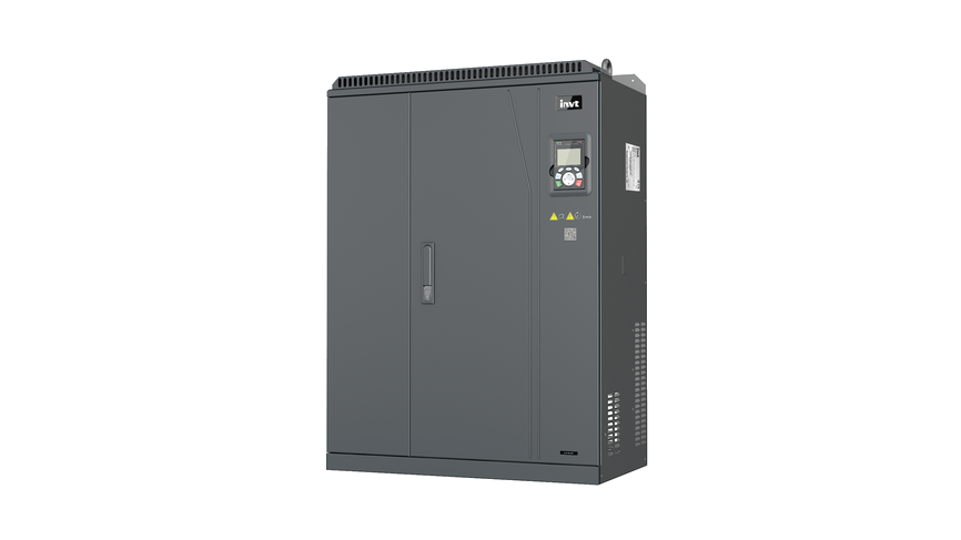
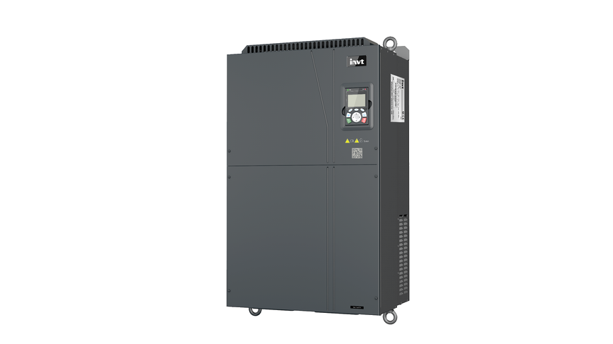
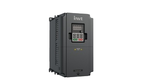
GD350A Series High-Performance General-Purpose VFD
The GD350A series is a high-performance multifunction Variable Frequency Drive (VFD). It can drive both synchronous and asynchronous motors and supports torque, speed, and position control. Equipped with industry-leading vector control technology and the latest digital processor dedicated to motor control, the VFD features enhanced reliability and environmental adaptability. By incorporating customized and industry-specific designs, it offers optimized functions and highly flexible applications. The VFD uses high power density design. Some power ranges carry built-in DC reactor and braking unit to save installation space. Through overall EMC design, it can satisfy the low noise and low electromagnetic interference requirements to cope with challenging grid, temperature, humidity and dust conditions, thus greatly improving product reliability.
·Single unit: 0.4–500kW, parallel operation: 560–3000kW
· 380~690V
·Certified to CE, TUV, KC, UKCA, etc


 Video
 Images
Overview
Features
Specifications
Downloads
More Resources
Case
Videos
More
Features

Strong drive capability, compatible with multiple motor types
 Capable of driving permanent magnet synchronous motors (PMSM), asynchronous motors, and synchronous reluctance motors (customized software required), including direct-drive motors, PMSM, motor spindles, asynchronous servo motors, standard asynchronous motors, synchronous reluctance motors, and servo motors.Supports multiple control algorithms: V/F, open-loop vector, and closed-loop vector control.
01
Powerful motor control performance with high precision
Speed and torque control performance: closed-loop vector dynamic speed drop <0.25%, speed overshoot <5%, torque response <5ms.Low-speed control performance: Speed regulation ratio over 1:200 for permanent magnet synchronous motors; switching between motoring and generating modes at 100% torque; 150% zero-speed (short-term) hovering.Synchronous reluctance control (currently supported via customized software): Supports open-loop control (speed regulation ratio 1:100) and closed-loop vector control; dynamic current distribution with optimal vector angle automatically matched for different speed and torque conditions.02
Strong adaptability to synchronous motors
One-key motor parameter autotuning and loop parameter self-adaptation for commissioning-free startup.03
G/P integration for flexible model selection
Supports G/P integration, making inventory management more convenient and enhancing competitiveness in light-load applications.04
Strong expansion capability with flexible configuration
Optional I/O cards available for additional digital/analog inputs and outputs, as well as relay output terminals.Optional power supply cards for external 24V power, simplifying on-site commissioning.Optional communication expansion cards: PROFINET, CANOPEN, PROFIBUS-DP, Ethernet/IP, Modbus TCP, EtherCAT, etc.05
Functional safety
Built-in Safe Torque Off (STO) function compliant with SIL 3.Optional power supply cards for external 24V power, simplifying on-site commissioning.Optional communication expansion cards: PROFINET, CANOPEN, PROFIBUS-DP, Ethernet/IP, Modbus TCP, EtherCAT, etc.06
Supports motor temperature detection for enhanced motor protection
AI/AO interfaces support direct connection to PT100, PT1000, KTY84, and PTC sensors for monitoring motor temperature and implementing protection measures. There is no need to select a separate transmitter, making the application simple and convenient.07
Supports user-programmable secondary development
Optional programmable PLC expansion card, utilizing mainstream international PLC development environments. It supports various programming languages such as Instruction List (IL), Ladder Logic (LD), and Sequential Function Chart (SFC), and features a 16K-step program memory, enabling secondary development for customized needs and lowering system cost.08
Energy saving
Supports energy-saving control (MTPA), further reducing motor losses.-Both VF and vector control support new energy-saving algorithms, reducing light load current by 30%.Lower current harmonics (<7%), reducing motor heating; random PWM modulation strategy for quieter motor operation.09
More firmware upgrade options
Remote upgrade: Supports upgrades via RS485, local serial port, or 4G expansion card.Local upgrade: Supports software upgrade via USB flash drive. 10
User-friendly HMI
Standard multi-function LCD keypad with a user-friendly design, prioritizing user experience. 11
Specifications
Downloads
By Type:
 Load More




Have questions or need support?
Our professional team is here to help.


Inquiry
TOP
Popular Searches:
Repair Progress Tracking | Identity Verification
To protect your repair information, please verify using the mobile number reserved on the service order.
Verify with the reserved mobile number
Verify
SMS Verification Code *
If you cannot receive the code, please contact the after-sales hotline. 400-700-9997


Contact INVT
Get in touch with INVT. Our team will get back to you shortly.
Full Name *
Company Name *
Email Address *
Phone Number *
Country *
City
Inquiry Type *
Product Category *
Select the product you're interested in.
-
Industrial Automation
-
Network Power
-
PV & ESS
-
e-Mobility
Your Message / Requirements *
I have read and agree to INVT Privacy Policy and Terms of Use
Captcha *