Item | Specifications | |
Power input | Input voltage (V) | AC 3PH 380V–480V; rated voltage: 380V |
Input frequency (Hz) | 50Hz or 60Hz; allowed range: 47–63Hz | |
Input power factor | 30–110kW≥0.9 | |
Power output | Output voltage (V) | 0–input voltage |
Output frequency (Hz) | 0–400Hz | |
Technical control performance | Control mode | Space voltage vector control mode Sensorless vector control (SVC) mode Feedback vector control (FVC) mode |
Motor type | Asynchronous motor (AM) and permanent magnet synchronous motor (SM) | |
Speed ratio | 1:200 (SVC), 1:1000 (FVC) | |
Speed control accuracy | ±0.2% (SVC), ±0.02% (FVC) | |
Speed fluctuation | ±0.3% (SVC), ±0.02% (FVC) | |
Torque response | <20ms (SVC), <10ms (FVC) | |
Torque control accuracy | 10% (SVC), 5% (FVC) | |
Starting torque | For AMs: 0.25Hz/150% (SVC) For SMs: 2.5Hz/150% (SVC), 0Hz/200% (FVC) | |
Overload capacity | Able to run at 150% of the rated current for 1 minute, 180% of the rated current for 10 seconds, and 200% of the rated current for 1 second (G type). | |
Braking capability | 100% braking power for continuous operation, 120% braking power for 1 minute, and 160% braking power for 10 seconds. | |
Running control performance | Frequency setting method | Settings can be implemented through digital, analog, pulse frequency, multi-step speed running, simple PLC, PID, Modbus communication, PROFIBUS communication and so on. Settings can be combined and the setting channels can be switched. |
Automatic voltage regulation (AVR) | The output voltage can be kept constant although the grid voltage changes. | |
Fault protection | More than 30 protection functions, such as protection against overcurrent, overvoltage, undervoltage, overtemperature, phase loss, and overload. | |
Dedicated functions | Braking protection | VFD models of 30kW, 37kW, 90kW, and 110kW provide protection against braking resistor short circuit, braking unit short circuit, and PB-PE short circuit. |
Brake control | Dedicated hoisting brake logic, integrated with torque verification, brake feedback, zero position detection, restart after braking functions, which meet the industrial VFD standards for crane applications. | |
Conical rotor motor control | Boosts magnetic flux during startup to ensure brake release, and reduces flux during stop to achieve brake engagement. | |
Light load speed boost | In closed-loop mode, the speed can be boosted and limited at constant power status, and the speed is limited in stepped way. In open-loop mode, if the simplified speed boost way is used, the speed boosts to the set frequency in light load status; if the speed is boosted or limited in constant power status, the speed is limited in stepped way. | |
Zero servo | In closed-loop mode, if the VFD detects load downward slip, the VFD automatically enters the zero servo state and outputs a brake failure alarm. When a level-2 fault occurs, if load downward slip occurs, the VFD automatically resets the fault, enters the zero servo state, and outputs a brake failure alarm. | |
Anti-sway for horizontal moving | By selecting different anti-sway modes, it can effectively eliminate the load swing caused by the acceleration and deceleration of the parallel traveling mechanism in different scenarios such as with rope length, without rope length, speed, and position control scenarios. | |
Tower crane slewing without using an eddy current controller | Built-in curves for tower crane slewing without using an eddy current controller help to adjust the ACC in real time so that the torque is steady, which can suppress boom rebound and vibration when the boom pauses or stops. | |
Wind resistance of tower crane slewing | Built-in curves for tower crane slewing without using an eddy current controller and anti-sway adaptation technology help to adjust the variable frequency ACC in real time so that the slewing mechanism runs steadily and responds quickly; even in the windy environment, it can eliminate the problem that the mechanism is easy to slide in the downwind and it cannot reach the given speed in the upwind. | |
Slack rope protection | If the slack rope state is detected during hook lowering, the VFD reports a fault or alarm. This eliminates the safety hazards caused by hanging or squatting in operation. | |
Upward/downward limit position | The function is used to limit the crane to run within the specified range. The VFD enables emergency stop and reports an alarm once the range is exceeded. | |
Upward/downward DEC limit position | When the deceleration signal is valid, the running speed of the crane is limited once the crane runs within the slow speed area. Single direction limit: For example, in the upward slow speed area, the speed limit applies only to upward travel. | |
Load position | In closed-loop mode, the encoder is used to measure the load position. | |
Master/slave control | Master/slave power balance and speed synchronization. | |
Hoisting application macro | Including lifting, horizontal moving, construction elevator, tower crane slewing, and user-defined application macros. | |
Lifting and horizontal moving switchover | Three groups of motor parameters, control modes, and application macros can be switched. | |
Frequency decrease with voltage | When the bus voltage is continuously low, the reference frequency is decreased to keep the normal output torque of VFD. | |
Low-voltage protection | When the bus voltage decreases transiently or the VFD quickly stops due to power outage, the function is used to ensure the hook does not slip. The low voltage protection function is automatically disabled once the bus voltage restores to the normal state. | |
Low-speed run protection | The VFD reports the low-speed run protection fault when the low-speed run time exceeds the allowed time. This prevents the axial cooling motor from being damaged due to overheating caused by long-time running. | |
Overload protection | In closed-loop mode, when overload occurs, upward lifting is restricted. | |
| The HDO outputs PWM waves to directly control eddy current. | ||
Brake feedback (FB) | When the brake control signal is inconsistent with the brake feedback signal, the VFD handles the inconsistency according to the brake status to ensure safety. | |
Zero position detection | The zero position signal and running signal are mutually exclusive. | |
Torque verification | The VFD verifies the current or torque before brake release. The VFD performs brake release when the verification succeeds, and the VFD reports the verification fault when the verification fails. | |
One-click open/closed loop switchover | The closed-loop control mode can be switched to the open-loop control mode through terminals. When the encoder is faulty, the open-loop control mode can be used. The switchover takes effect only in stopped state but not in running state. | |
Jogging | After receiving a jogging command, the VFD can automatically start, run, and stop at the preset running frequency and time according to the settings. During the process, the brake can be normally opened or closed under the control of VFD, ensuring the stability without hook slip or exception when the crane starts or stops. | |
Smooth lifting | In high-speed lifting mode, the high speed is limited at the moment of steel rope straightening, reducing the impact caused by the sudden load to the crane at the lifting start. | |
Set frequency exception protection | If the set frequency is lower than the threshold after the brake is opened, the VFD reports the set frequency exception, which prevents slip caused by insufficient force at low speed. | |
Motor overheating protection | An I/O expansion card can receive the input from a motor temperature sensor (PT100, PT1000, or PTC); at the same time, AI analog can also receive the input from a motor temperature sensor (PT100, PT1000, KTY84, or PTC), for motor overheating protection. | |
Peripheral interface | Terminal analog input resolution | No more than 20mV |
Terminal digital input resolution | No more than 2ms | |
Analog input | Two inputs; AI1: 0–10V/0–20mA; AI2: -10–+10V | |
Analog output | One input; AO1: 0–10V/0–20mA | |
Digital input | Four regular inputs; max. frequency: 1kHz; internal impedance: 3.3kΩ Two high-speed inputs; max. frequency: 50kHz; supporting quadrature encoder input; with speed measurement function | |
Digital output | One high-speed pulse output; max. frequency: 50kHz One Y terminal open collector output | |
Relay output | Two programmable relay outputs RO1A: NO; RO1B: NC; RO1C: common RO2A: NO; RO2B: NC; RO2C: common Contact capacity: 3A/AC250V, 1A/DC30V | |
Expansion interfaces | SLOT1, SLOT2, and SLOT3 Supports PG cards, programmable expansion cards, communication cards, I/O cards, and other cards. | |
I/O | Relay output | Two programmable relay outputs; contact capacity: 3A/250VAC, 1A/30VDC RO3A: NO; RO3C: common; RO4A: NO; RO4C: common |
Digital input | Three regular inputs Internal impedance: 6.6kΩ Max. input frequency: 1kHz Supporting the internal power 24V Supporting the voltage input of external power (-20%) 24–48VDC (+10%) and (-10%) 24–48VAC (+10%) Bidirectional input terminals, simultaneously supporting NPN and PNP connection methods One channel supports PTC input, while PTC acts at 2.5kΩ, and supports the input of only dry contacts sharing COM. | |
PT100 input | Independent PT100 and PT1000 input: 1. Resolution: 1°C 2. Range: -20°C–+150°C 3. Detection precision: ±3°C 4. Supporting offline protection | |
PT100 input | ||
Other | Mounting method | Supports wall mounting, floor mounting, and flange mounting. |
Temperature of running environment | -10°C–+55°C. Derating is required when the ambient temperature exceeds 40°C. | |
Ingress protection (IP) rating | IP20 | |
Pollution degree | Degree 2 | |
Cooling method | Forced air cooling | |
DC reactor | 380V 30–110kW models: Standard (built-in) 380V 132kW and above models: Optional (external) | |
Braking unit | 380V 110kW and below models: Standard (built-in) | |
EMC filter | Optional built-in C3 filter. If a C3 filter is required, connect the jumper J10. After the C3 filter is configured, the VFD can meet IEC61800-3 C3 requirements. Optional external filters can be used to meet the IEC61800-3 C2 requirements. | |

GD350-CCS Series VFD for Marine Industry
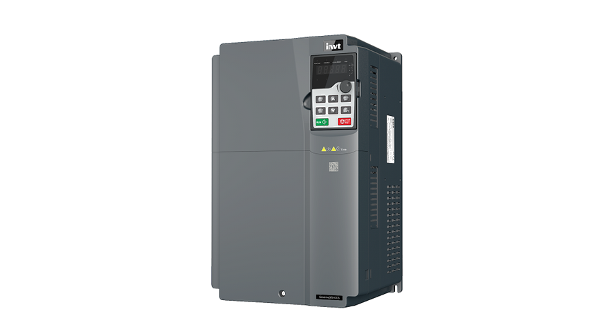
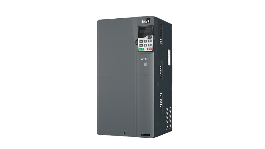
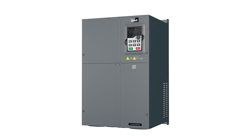
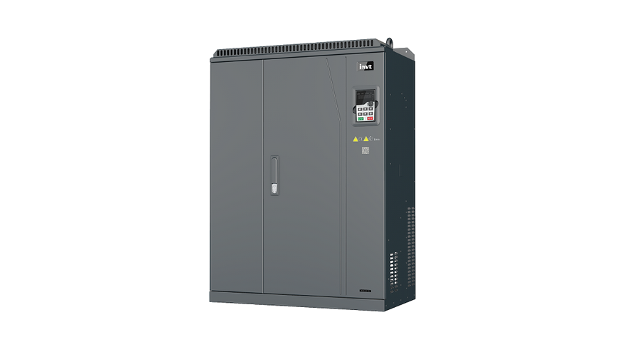
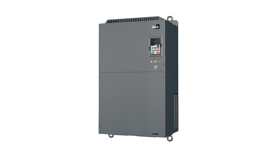
The GD350-CCS series VFD is a marine-specific Variable Frequency Drive (VFD) developed based on the GD350 platform for shipboard applications. It integrates dedicated functions for fans, pumps, and hoisting while enhancing product reliability and environmental adaptability to meet marine requirements such as salt spray resistance, vibration, humidity, temperature, and power grid fluctuations. With strong expandability, rich safety protection functions, and excellent control performance, it satisfies diverse application needs. Certified by China Classification Society (CCS), it meets the special requirements of the marine and offshore industry.


 Images
Features

 Salt spray protection design, improved insulation performance, vibration and shock resistance. Full-drive capability, enhanced performance, smooth starting, torque tracking.Rich expansion options, supporting multiple communication protocols for easy networking, wireless commissioning, secondary development, host controller monitoring and commissioning, and transient power loss ride-through.Features include slack rope protection, travel limit, overload protection, three-motor switching, anti-sway function, light-load speed-up, conical rotor motor control, load height measurement, positioning stop, smooth acceleration/deceleration, multiple operation modes, and slewing control.Wide voltage design, thermal simulation analysis, comprehensive mechanical and EMC testing, vertical air duct design, and safe torque off (STO).
Specifications
Downloads
 Load More
Have questions or need support?
Our professional team is here to help.


Repair Progress Tracking | Identity Verification
To protect your repair information, please verify using the mobile number reserved on the service order.


Contact INVT
Get in touch with INVT. Our team will get back to you shortly.
-
Industrial Automation
-
Network Power
-
PV & ESS
-
e-Mobility