Item | Specifications | |
Power input | Input voltage (V) | AC 3PH 380V (-15%)–440V (+10%); rated voltage: 380V |
Input frequency (Hz) | 50Hz or 60Hz; allowed range: 47–63Hz | |
Power output | Output voltage (V) | 0–input voltage |
Output frequency (Hz) | 0–400Hz | |
Technical control performance | Control mode | Space voltage vector control, and sensorless vector control (SVC) |
Motor type | Asynchronous motor (AM) and permanent magnet synchronous motor (SM) | |
Speed ratio | Asynchronous motor (AM): 1:200 (SVC) Synchronous motor (SM): 1:20 (SVC) | |
Speed control accuracy | ±0.2% (SVC) | |
Speed fluctuation | ±0.3% (SVC) | |
Torque response | <20ms (SVC) | |
Torque control accuracy | 10% (SVC) | |
Starting torque | For AMs: 0.25Hz/150% (SVC) For SMs: 2.5Hz/150% (SVC) | |
Overload capacity | Able to run at 150% of the rated current for 1 minute, 180% of the rated current for 10 seconds, and 200% of the rated current for 1 second. | |
Running control performance | Frequency setting method | Settings can be implemented through digital, analog, pulse frequency, multi-step speed running, simple PLC, PID, Modbus communication, PROFIBUS communication and so on. Settings can be combined and the setting channels can be switched. |
Automatic voltage regulation (AVR) | The output voltage can be kept constant although the grid voltage changes. | |
Fault protection | More than 30 protection functions, such as protection against overcurrent, overvoltage, undervoltage, overtemperature, phase loss, and overload. | |
Start after speed tracking | Enables smooth startup of a rotating motor. Note: Applicable to models ≥ 4kW. | |
Peripheral interface | Terminal analog input resolution | No more than 20mV |
Terminal digital input resolution | No more than 2ms | |
Analog input | Two inputs (AI1, AI2) 0–10V/0–20mA; one input (AI3) -10–+10V | |
Analog output | Two outputs (AO1, AO2) 0–10V/0–20mA | |
Digital input | Eight regular inputs; max. frequency: 1kHz; internal impedance: 3.3kΩ One high-speed input; max. frequency: 50kHz | |
Digital output | One high-speed pulse output; max. frequency: 50kHz One Y terminal open collector output | |
Relay output | Two programmable relay outputs RO1A: NO; RO1B: NC; RO1C: common RO2A: NO; RO2B: NC; RO2C: common Contact capacity: 3A/AC250V, 1A/DC30V | |
Other | Mounting method | Supports through-wall (flange) mounting. |
Temperature of running environment | -10°C–+50°C. Derating is required when the ambient temperature exceeds 40°C. | |
Mean time between failure (MTBF) | 2 years (ambient temperature: 25°C) | |
Ingress protection (IP) rating | IP20 | |
Cooling method | Forced air cooling (external air duct cooling, air velocity > 2m/s) | |
Braking unit | Models ≤ 18.5kW: Built-in Models ≥ 22kW: Optional external | |
EMC filter | 380V built-in C3 filter: Meets IEC 61800-3 C3 requirements. Optional external filters can be used to meet the IEC61800-3 C2 requirements. | |

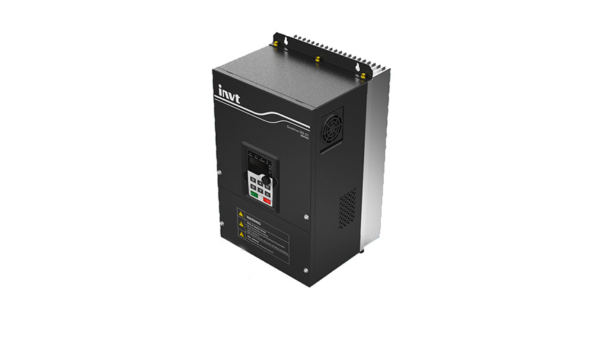
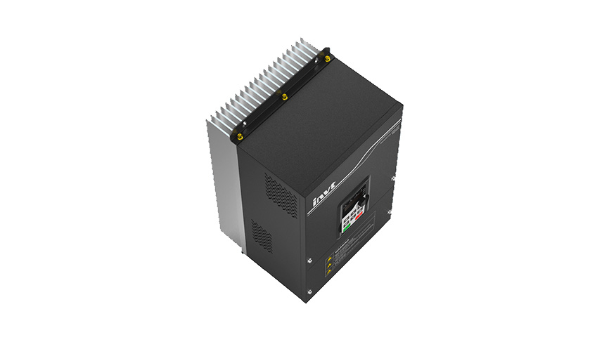
GD350-02 Series Through-Wall VFD
GD350-02 series through-wall Variable Frequency Drive (VFD) is a specialized VFD designed to address secondary contamination from cotton fluff, dust, oil, and other foreign materials, improving product reliability and environmental adaptability. Utilizing high-performance vector control technology, it features excellent dynamic characteristics and incorporates built-in power-down synchronization and fault synchronization controls tailored for the textile industry, enabling safe shutdown under abnormal conditions.


 Images
Features

 Through-wall installation that separates the heat dissipation system from the electrical system to effectively address contamination from cotton fluff, oil, etc.The entire series features a metal enclosure with a large-sized aluminum heat sink and a fanless design, allowing stable, long-term, and reliable operation in environments up to 50°C, thus extending the service life and reducing maintenance and replacement costs.Dedicated heat dissipation structure designed to prevent cotton fluff blockages, minimizing manual cleaning efforts.Compatible with both synchronous and asynchronous motors, series-wide shared DC bus support, transient power loss ride-through, and various optional communication protocols.
Specifications
Downloads
 Load More
Have questions or need support?
Our professional team is here to help.


Repair Progress Tracking | Identity Verification
To protect your repair information, please verify using the mobile number reserved on the service order.


Contact INVT
Get in touch with INVT. Our team will get back to you shortly.
-
Industrial Automation
-
Network Power
-
PV & ESS
-
e-Mobility