Abstract: The Electrical Submersible Pump (ESP) artificial lift method is widely used in non-flowing high-yield wells, high water-cut wells, and offshore oil fields due to its advantages of simple equipment structure, high efficiency, large discharge capacity, and a high degree of automation. It has become one of the artificial lift methods with stable and high production as well as good economic benefits, serving as a primary means for enhanced oil recovery during the middle and late stages of oilfield development.
Keywords: GD3000, Electrical Submersible Pump (ESP), Oil Submersible Pump
1. Project Background
The Electrical Submersible Pump (ESP) is lowered into the well via tubing, comprising a centrifugal pump and a submersible motor. The motor drives the pump to lift oil to the surface. ESP systems offer a wide range of adjustable flow rates and lift heads, strong adaptability, simple surface process flow, easy management, straightforward automation, and high economic efficiency.
After half a century of development, ESP artificial lift has become crucial equipment in the petroleum industry. Particularly through continuous technical improvements and the application of modern technologies, its adaptability has been significantly enhanced. Technologies suitable for heavy oil, high gas-oil ratio, high temperature, corrosion resistance, and sand control have emerged, contributing substantially to oilfield development.
As major oilfields in China successively enter mid-to-late exploitation stages with increasingly complex geological conditions, Electrical Submersible Pumps will see even broader application.
2. Solution Introduction
2.1 Equipment Working Principle
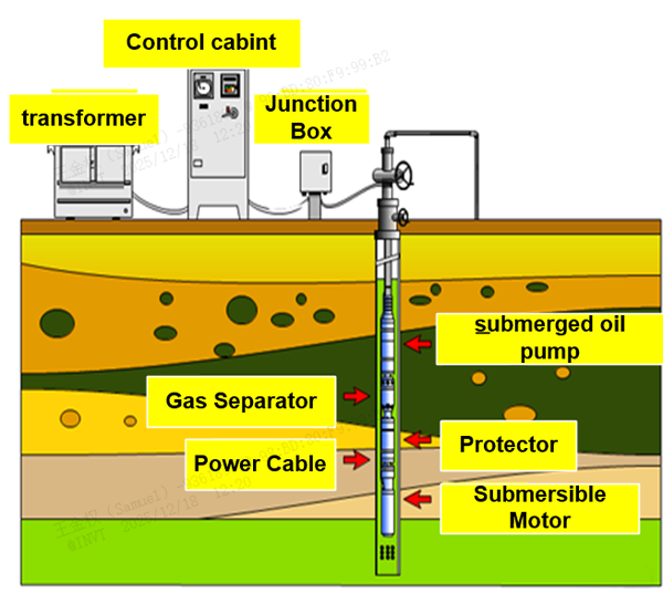
The Electrical Submersible Pump (ESP) system consists of three main sections: the downhole section, the surface section, and the intermediate section that connects them. The downhole section, which is the primary unit of the ESP, comprises three key components: the multistage centrifugal pump, the protector, and the submersible motor. This section performs the main function of lifting the oil.
The submersible motor, installed at the bottom of the downhole assembly, serves as the power source of the Electric Submersible Pump (ESP). High-voltage electric current from the surface is transmitted to the submersible motor via a power cable. The motor converts electrical energy into mechanical energy, which drives the pump into operation through its rotating shaft.
The protector is mounted above the submersible motor. Its functions are to equalize the internal pressure of the motor and to provide lubrication and sealing. The gas separator is usually installed at the upper end of the protector and the lower end of the multistage centrifugal pump. It is used to separate free gas from the crude oil, thereby improving pump efficiency.
The multistage centrifugal pump consists of stationary and rotating components. The rotating assembly includes a pump shaft onto which a large number of impellers are mounted. When the motor drives the shaft, causing the impellers to rotate at high speed, the fluid within the impellers is forced outward by centrifugal force. This action accelerates the well fluid, imparting kinetic energy to it. The fluid is then guided by the diffuser into the next stage impeller. The energy (or head) is cumulatively increased stage by stage in this manner until a sufficient total head is achieved to lift the well fluid to the surface.
2.2 INVT Solution
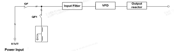
Based on actual requirements, the system is designed and developed by the customer. The GD3000 series VFD from INVT is utilized. The frequency control cabinet integrates components including the main circuit breaker, input filter, input reactor, VFD, and output reactor.
2.2.1 Solution Features
Medium-voltage power supply at 1140V; motor voltage at 780V; motor cable distance ranging from 1000 to 3000 meters.
The input side is equipped with a reactor and an input filter, significantly improving the power factor on the grid side of the system.
2.2.2 System Diagram
Block Diagram
2.2.3 Solution Configuration Sheet
| NO. | Name | Selection Guide | Quantity | Remarks |
|---|---|---|---|---|
| 1 | VFD | GD3000-00-055G-12 | 1 |
3. Product / Solution Advantages
The VFD adopts a new three-level topology, which features low harmonics and reduces damage to the motor.
It offers comprehensive control modes and is compatible with both synchronous and asynchronous motor drive and control.
It features a built-in braking unit, which meets the requirements of energy regeneration applications.
It provides extensive communication interfaces, supporting Ethernet, MODBUS, PROFIBUS DP, among others.
With its compact design, it facilitates customer system integration.
The power supply input features a wide-range grid design with an input voltage of 970 to 1310V, allowing it to adapt to various grid environments.
4. Parameter Logging
| NO. | Index | Function code name | String Value |
|---|---|---|---|
| 1 | P00.00 | Speed Control Mode | 2:V/F control |
| 2 | P00.01 | Channel of running commands | 2:Communication |
| 3 | P00.02 | Communication mode of running commands | 0:Modbus/Modbus TCP |
| 4 | P00.03 | Max. output frequency | 150 |
| 5 | P00.04 | Upper limit of running frequency | 150 |
| 6 | P00.05 | Lower limit of running frequency | 0 |
| 7 | P00.06 | Setting channel of A frequency command | 8:Modbus/Modbus TCP communication |
| 8 | P00.07 | Setting channel of B frequency command | 1:AI1 |
| 9 | P00.11 | ACC time 1 | 20 |
| 10 | P00.12 | DEC time 1 | 20 |
| 11 | P00.14 | Carrier frequency | 2 |
| 12 | P02.00 | Type of motor 1 | 1:Synchronous motor (SM) |
| 13 | P02.15 | Rated power of SM | 37 |
| 14 | P02.16 | Rated frequency of SM 1 | 150 |
| 15 | P02.17 | Number of pole pairs of SM 1 | 3 |
| 16 | P02.18 | Rated voltage of SM 1 | 778 |
| 17 | P02.19 | Rated current of SM | 30 |
| 18 | P02.20 | Stator resistance of SM 1 | 0.732 |
| 19 | P02.21 | Direct-axis inductance of SM 1 | 7.55 |
| 20 | P02.22 | Quadrature-axis inductance of SM 1 | 7.55 |
| 21 | P02.23 | Counter-emf of SM 1 | 780 |
| 22 | P05.00 | HDI input type | 0:HDIA is high-speed pulse input |
| 23 | P05.01 | Function of S1 | 6:Coast to stop |
| 24 | P05.02 | Function of S2 | 9:External fault input |
| 25 | P05.03 | Function of S3 | 7:Fault reset |
| 26 | P06.03 | RO1 output | 1:In running |
| 27 | P06.04 | RO2 output | 5:VFD fault |
| 28 | P06.17 | AO1 output lower limit | 0:running frequency |
| 29 | P06.18 | AO2 output lower limit | 0:running frequency |
| 30 | P06.19 | AO3 output lower limit | 0:running frequency |
| 31 | P06.20 | AO1 output corresponding to upper limit | 0:running frequency |
| 32 | P08.37 | Enabling energy consumption braking | 1:Dynamic Braking Enable |
| 33 | P08.38 | Energy consumption braking threshold voltage | 1950 |
| 34 | P11.08 | Pre-alarm selection for VFD/motor OL/UL | 0x130 |
| 35 | P11.10 | Overload pre-alarm detection time | 10 |
| 36 | P11.11 | Underload pre-alarm detection level | 0 |
| 37 | P11.12 | Underload pre-alarm detection time | 10 |
| 38 | P13.02 | Pull-in current 1 | 30 |
| 39 | P13.03 | Pull-in current 2 | 0 |
| 40 | P13.04 | Pull-in current switchover frequency | 50 |
| 41 | P14.00 | Local communication address | 1 |
| 42 | P14.01 | Communication baud rate | 3:9600BPS |
| 43 | P14.02 | Data bit check | 0:No check(N,8,1)for RTU |
5. Field Application Videos and Photos
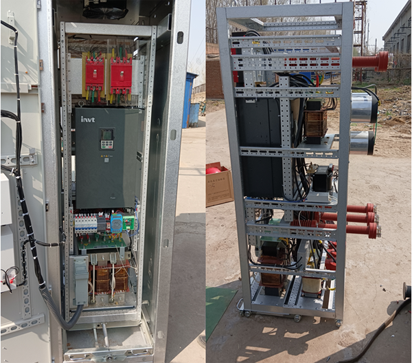
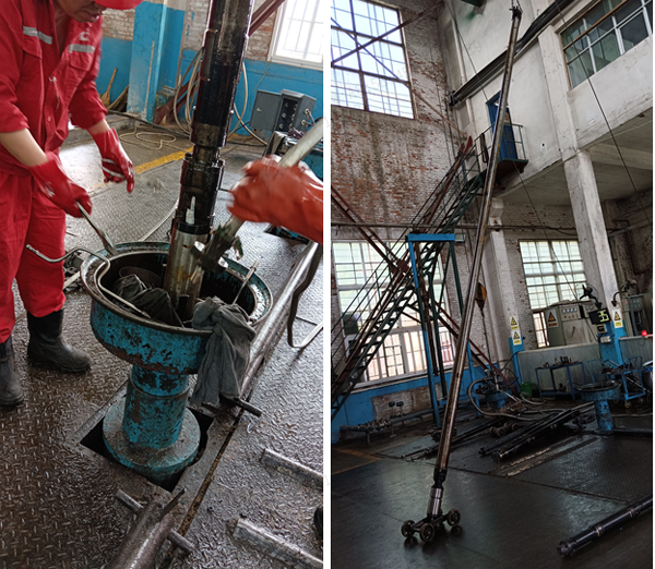
6. Conclusion
The function of the Electrical Submersible Pump (ESP) system is to achieve high-lift, high-volume fluid lifting. In China, over 40 years have passed since the ESP technology was introduced in 1981, and as a crucial piece of mechanical oil recovery equipment, it has seen widespread application in oilfields. With the advancement of green energy initiatives in China and the extensive development of geothermal wells, coalbed methane wells, and shale gas wells, its potential for broader application is immensely promising.
References
[1] "Goodrive3000 Series Medium-Voltage VFD". Shenzhen INVT Electric Co., Ltd., 2022.



Our site uses cookies to provide you with a better onsite experience. By continuing to browse the site you are agreeing to our use of cookies in accordance with our Cookie Policy.
















 Share
Share
 Facebook
 Twitter
 Google+
 LinkedIn
 Return list