Abstract: With the development of economy, contradiction of resource limitation has become more and more serious. Establish an energy-saving society, upgrade technology to save energy and reduce consumption is the development directions for all power generation enterprises. The operation result proves that the application of high voltage inverter technology in auxiliary engines in heat-engine plant is of great technology performance and significant economic benefit as well as good promotion value.
Keywords: Induced Draft Fan, Inverter, Energy-saving and Consumption Reduction, Economic Benefit
I. Summary
Power plant is not only an electric energy producer but also a user and a consumer of electric energy. In the composition of power supply energy in China, thermal power accounts for over 70%. While for the general thermal power generating units, they account for the power generation of 4% to 7%. To drive large capacity fans and water pump auxiliary engines in high voltage factory, the electric motors need to consume 80% of total electricity amount in the factory. Because of the emergence of separation of plant and network and price bidding in electricity system reform, coal consumption of electricity generation and auxiliary power rate in the factory have become important indicators for power factory performance appraisal, which is related to economic benefit and competitive of an enterprise. And energy-saving effect of variable speed control of fan machine and water pump auxiliary engine can significantly reduce factory power consumption and decrease electricity generating cost. Therefore, choosing a proper high voltage factory electric motor speed control system has become the top priority for power plant energy-saving work.
II. Inverter Speed Adjustment and Energy-saving Principle
Asynchronous motor rotate speed N and frequency F, motor slip ratio S and motor number of pole pairs P have such the following relation:
N=60F(1-S)/P
For above formula, rotate speed N and frequency F are in direct proportion so that it only needs to change frequency F and rotate speed of motor will be changed. At the same time, the output power of motor will also be changed. N and F have a linear relation. When F changes from 0 to 50Hz, the adjustment scope of rotate speed is very wide. When load change causes rotate speed reduction of fans and the output power will also be decreased. And inverter can better solve this problem so as to get a good energy-saving effect.
III. Upgrading Solution
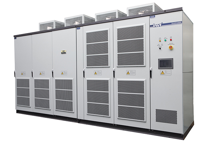
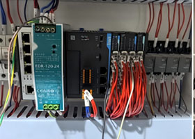
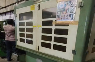
In 2015, July, we remolded an induced draft fan of 1*300MW unit with high voltage speed control inverter in a power plant. We reformed an electromotor at this time with drug and automation separation method and we adopted power frequency and variable frequency to operate induced draft fan. With contrast and analysis, GD5000-A3150-06-S series medium voltage drives manufactured by Shenzhen INVT electric Co., Ltd. be of better performance. The inverter rectifier was diode and inverter device was IGBT (shown as the figure 1) and its control method was speed sensorless vector control. In 2015, August, the new system was totally put into operation.
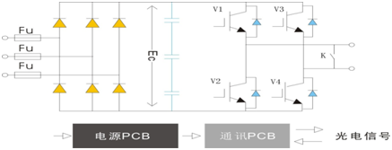
Figure 1 Power Unit Principle Graph
IV. System Operation Process Description
Inverter 6KV power passes the inverter device to disconnecting link and contactor and then it will come to high voltage inverter device and inverter device outputs to disconnecting link and contactor and then to electromotor. And 6KV power also can directly star electromotor by bypass contactor. The functions of inline and outline disconnecting link and contactor and bypass disconnecting link and contactor are:
1.If there was breakdown on the inverter, inline and outline disconnecting link and contactor can be cut off immediately. In this way, the inverter device can be separated and use manual bypass contactor the electromotor can work again with power frequency power supply.
2.The bypass cabinet has five-prevention closedown function;
3.The bypass cabinet has industrial frequency and variable frequency indicator function;
4.The bypass cabinet has electrified indicator function and electrified shutting door function.
System reform primary circuit is shown as the figure 2. To totally ensure the reliability of system, we also add power frequency bypass device to the inverter and if this is something abnormal on inverter, the device can stop operating and the electromotor can directly switch to operate under the power frequency state. In this way, the machine unit can operate safely.
To realize protection to inverter breakdown, the inverter interlocks 6KV switch QF. Once there is breakdown on inverter, the inverter will trip off QF. When the power frequency is in bypass, the inverter will always allow QF closing and withdrawal the trip signal to QF, so that the motor can normally start by QF closing frequency.
Variable frequency control system is consist of user switch, automatic bypass cabinet, GD5000 series high voltage inverter and high voltage motor. Bypass cabinet is composed of three vacuum high voltage contactors KM1, KM2, KM3 and high voltage isolating switch QS1, QS2. In the normal operations state, QS1, QS2 are all closed. Only in the maintenance, the switch QS1, QS2 are disconnected. When the motor is running in variable frequency mode, KM1 and KM2 are closed and QS3 is disconnected. When the motor is running in power frequency mode, KM3 is closed and KM1 and KM2 are disconnected. Switching between variable frequency and industrial frequency is done automatically or manually. Bypass cabinet is designed in strict accordance with the "five anti" interlock requirements, variable frequency output switch KM2 and industrial frequency switch KM3 are locked mutually, which is fully able to ensure the safe operation of frequency control system.
As in the entire frequency control system, the former user switchgear has overload protection device, so the manual bypass cabinet will not protect the overload motor. At the same time, the user switchgear must be in accordance with the 8-10 times the rated current to set the speed protection value so as to escape surge current.
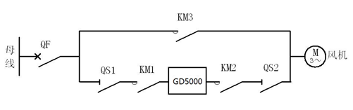
Figure 2 Upgrading Primary Circuit Graph
The busbar is on the leftside and the fan machine is on the right side.
V.Problems in the Debugging Process and Improvement Measures
(1) In the debugging process, we found that the speed command signal was lost and the inverter did not maintain the original speed of the motor, so we adjusted the control part of the inverter and finally the problem had been effectively resolved.
(2) Upload temperature alarm of transformer that controlled the variable frequency inverter
to DCS interface, which effectively realized monitoring on over-temperature of the transformer.
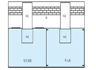
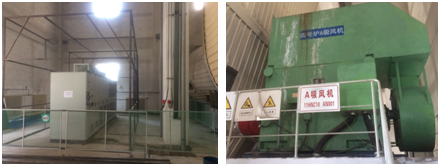
(3) In order to solve the problem of high temperature of the inverter in the summer, the design of the inverter cooling system of the electric fan in power plant of China Power Investment Corporation adopted the outdoor air cooling circle mode (shown as figure 3). This design greatly reduced the use rate of air conditioning. Now the frequency conversion device can operate without air conditioning cooling system, thus further to enhance energy-saving effect of frequency conversion device.
(4) In order to ensure that the inverter can run normally in case a part of the power unit is damaged, the power unit primary function is set in the bypass. In this way, the inverter can run normally when a group of power units of inverter are failure.
VI.An Analysis of Economic Benefit after Energy -saving Upgrading
To facilitate the analysis of energy saving after frequency conversion upgrading, we compared the parameters of two kinds of operating modes of the draft fan under the different operating conditions with 150MW and 300MW load.
Table 1 shows the energy-saving effect. From table 1, we can know that when the unit load is 150MW and 300 MW respectively, draft fan operation under variable frequency can save 256kW • h, 535kW • h more than that under industrial frequency state. After the frequency conversion upgrading, energy saving effect is remarkable.
Table1 Energy Saving Contract
| Parameter | Measurement and Calculation | ||
| Unit Load(MW) | 150 | 300 | |
| Power Frequency Running State | Average Current(A) | 145 | 286 |
| Electricity Consumption(kW.h) | 1356 | 2674 | |
| Variable Frequency Running State | Average Current(A) | 110 | 214 |
| Electricity Consumption(kW.h) | 1100 | 2139 | |
| Energy Saving Effect(%) | 19% | 20% | |
VII.Conclusion
The energy saving effect was very remarkable and the starting frequency was low, the speed was low, the current was small and smooth after the variable frequency upgrading of the induced draft fan, which achieved a soft start and avoided large current impact and high torque influence that the old power frequency brings to motor, cables, switches and mechanical equipment. The application of variable frequency drive not only extends the life of the motor and other equipment, but also reduces bearing wear and improves the reliability of safe power supply.


Our site uses cookies to provide you with a better onsite experience. By continuing to browse the site you are agreeing to our use of cookies in accordance with our Cookie Policy.


 Share
Share
 Facebook
 Twitter
 Google+
 LinkedIn
 Return list