Abstract: Film machine, also known as extrusion compound machine, is a kind of extrusion molding machinery. In the production process of the film machine, it is necessary to ensure the line speed synchronization of each station at all times, and also need to detect the color mark signal in real time to ensure the position synchronization of front and reverse film pasting patterns. Our company provides the system solution of HMI + PLC + inverter + servo motor according to the on-site process of the film machine. In this paper, the application of INVT IVC1L series PLC, VK series HMI and GD35 inverter in the film machine is taken as an example to introduce the overall solution of INVT small automation system represented by the above products.
Key word: Film machine, INVT Automation system, Color mark
1 Preface
The technological process of the film machine is as follows: the extrusion screw heats and plasticizes the plastic particles, and then extrudes the liquid plastic into a linear shape by the die mouth of the flat die head. After stretching, it adheres to the surface of flexible substrate such as paper, film, non-woven fabric, woven cloth, etc., and then adheres the plastic color film to the coating object by using the viscosity of the plastic under hot state, cools and shapes the plastic, and presses the finished product. There are customized patterns on the surface of the plastic color film, and the front and back patterns of the finished product must be symmetrical. There is a color mark signal every fixed length of the color film as the reference origin of the color mark pattern, so that the front and back color film color mark positions are consistent to ensure the front and reverse symmetry. Therefore, it is necessary to trace the color mark signal.
2 Control technology of film machine system
The driving part of the film machine includes unwinding, front clamping, front laminating, reverse clamping, reverse laminating, front extrusion, reverse extrusion, color mark sensor, cooling, winding, tension floating roller, etc. the control process of each part is as follows:
Unwinding: magnetic powder clutch is used to ensure constant tension unwinding during equipment production.
Extrusion 1: drive 1#plastic extruder, heat the plastic particles into tape casting film, and then extrude, spray on the front surface of the substrate, and ensure the viscosity of the substrate.
Clamping 1: drive 1#clamping servo motor to drive the plastic film to move forward synchronously, and cooperate with the front film covering to complete the front color film lamination. There are periodic patterns on the surface of plastic color film, and the front and back color films are exactly the same.
Laminating 1: drive 1#laminating motor to drive the plastic color film into the clamping roller, and stick the plastic color film on the front surface of the substrate after coating. Because of the periodic change pattern on the surface of the plastic color film, a layer of "clothes" with different patterns is put on the front of the substrate after lamination.
Extrusion 2: drive 2#plastic extruder to heat the plastic particles into tape casting film and pour them on the back side of the substrate to ensure the viscosity of the substrate.
Clamping 2: drive 2#clamping servo motor to drive the plastic color film to move forward synchronously, and cooperate with the reverse side film covering to complete the color film lamination on the reverse side. At the same time, it is necessary to collect the front and reverse color mark signals in real time, and automatically adjust the 2#calmping feed speed to ensure the position synchronization of the front and back color marks.
Laminating 2: drive 2#laminating motor to drive the plastic color film into the clamping roller, and then glue the plastic color film on the opposite side of the substrate after coating.
Color mark sensor: collect front and reverse color mark signals to ensure the position synchronization of front and reverse color film.
Cooling: After the film coating is finished, the cooling roller is transmitted synchronously through the cooling roller. At the same time, circulating cooling water is added into the cooling roller to complete the cooling of film coating distribution and prepare for winding.
Winding up: wind up the coated fabric to complete the collection of finished products.
Tension floating roller: two rollers are used, respectively for laminating 1 and winding position. Floating roller 1 is used to ensure the constant tension during conveying after front film covering, and floating roller 2 is used to ensure constant tension during winding.
It can be seen from the above process that the front and reverse sides of the substrate are not coated synchronously during the production of the film machine, but the front side is first drenched, and then the reverse side is coated. Because of the periodic change pattern on the color film, and the non-synchronous of the front and reverse sides of the film, there will be deviation in the position of the front and reverse patterns. Therefore, it is necessary to adjust the feed rate of color film automatically by adjusting the speed of clamping motor in real time, so as to ensure the synchronization of front and reverse patterns after coating, which is also the top priority of the current coating machine control technology. At the same time, the tension of the whole process section must be constant, so as to avoid the color film / substrate stretching deformation caused by excessive tension in some positions or the color film / substrate wrinkle caused by too small tension, which affects the color film position.
3 System principle and control realization
3.1 Control requirements
In order to ensure the production efficiency, improve the accuracy of color mark calibration, the user's control requirements for the film machine are as follows:
1) Linear speed synchronization: in addition to the automatic adjustment of film feeding speed according to the color mark status of clamping 2, the linear speed of unwinding, clamping 1, laminating, cooling and winding up auxiliary machine stations must be consistent at all times to ensure stable tension, and can be modified in real time according to production requirements, and the tension should be stable during addition and subtraction.
2) High production speed: high maximum operation speed, improve production efficiency, and ensure the stability of tracing color mark in high-speed mode.
3) Fast and stable color mark calibration: the film feeding speed can be adjusted automatically by detecting the position of front and reverse color marks to ensure real-time color mark calibration.
4) Automatic filtering of miscellaneous marks: there are many impurities on the surface of the color film which are consistent with the color mark. It is necessary to automatically filter out the miscellaneous marks to prevent the equipment from running disorderly.
5) Self adaptive extrusion speed: according to the actual production speed, production gram weight and other parameters, the extrusion amount is automatically adjusted to ensure that the weight and output of the finished product can be controlled.
6) Multi mode switching: with single action and linkage mode switching.
3.2 Control realization
According to the control requirements of the system, the configuration list of key materials is as follows:
| No. | Name | Type | Qty. | Brand |
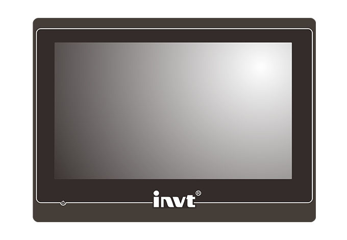
| 1 | HMI | VK100-N0CXQ | 1 | INVT |
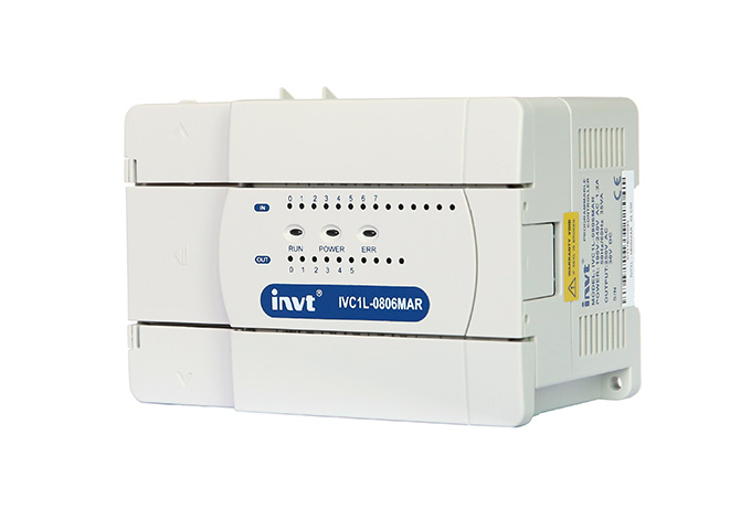
| 2 | PLC | IVC1L-3624MAT | 1 | INVT |
| 3 | Extrusion 1 inverter | GD200A-030G-4-H1 | 1 | INVT |
| 4 | Extrusion 2 inverter | GD200A-030G-4-H1 | 1 | INVT |
| 5 | Laminating 1 inverter | GD35-5R5G-4-H1 | 1 | INVT |
| 6 | Laminating 2 inverter | GD35-5R5G-4-H1 | 1 | INVT |
| 7 | Clamping 1 inverter | GD35-004G-4-H1 | 1 | INVT |
| 8 | Clamping 2 inverter | GD35-004G-4-H1 | 1 | INVT |
| 9 | Cooling inverter | GD35-5R5G-4-H1 | 1 | INVT |
| 10 | Winding up inverter | GD35-5R5G-4-H1 | 1 | INVT |
| 11 | Clamping servo motor | SV-MM13-2R0E-4-1A0-3000 | 2 | INVT |
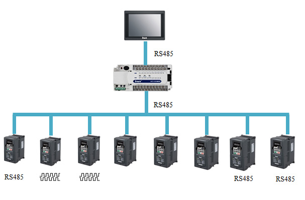
The system scheme is as follows:
3.3 Detailed scheme description
3.3.1 Description of control scheme for each station
The display part of the scheme is a 10 inch touch screen, and the control core is PLC. Data exchange between PLC and touch screen is realized through 485 communication. The main drive is 8 inverters, among which 6 motors except extrusion need to keep speed synchronization, and the two main machines automatically adjust the set speed according to the production speed and gram weight requirements. The speed control scheme of each transmission part is as follows:
| No. | Name | Control solution |
| 1 | Laminating 2 | Frequency division master, PLC converts the production speed set on the touch screen into frequency, writes it into laminating 2 through RS485 communication, and at the same time, the operating frequency of laminating 2 is given to the slave in real time |
| 2 | Clamping 1 | Receive the frequency division pulse of laminating 2 as the position source, stack the electronic gear correction, and ensure the linear speed and lamination 2 synchronization through the position synchronization |
| 3 | Cooling | Receive the frequency division pulse of laminating 2 as the position source, stack the electronic gear correction, and ensure the linear speed and lamination 2 synchronization through the position synchronization |
| 4 | Laminating 1 | It is required that the tension should be constant, and receive the frequency division pulse of laminating 2 as the speed source, and the electronic gear correction and the PID adjustment of the floating roller should be added to ensure the constant transmission tension. |
| 5 | Winding up | It is required that the tension should be constant, and receive the frequency division pulse of laminating 2 as the speed source, and the electronic gear correction and the PID adjustment of the floating roller should be added to ensure the constant winding up tension. |
| 6 | Clamping 2 | It receives clamping 1 frequency division pulse as speed source, and adds the deviation adjustment of color mark sensor to ensure the position synchronization of front and reverse film. |
| 7 | Extrusion 1 | PLC converts the production speed, gram weight and other data set on the touch screen into frequency, and writes it to master 1 through RS485 communication to ensure that the amount of front film can follow the production speed in real time |
| 8 | Extrusion 2 | PLC converts the production speed, gram weight and other data set on the touch screen into frequency, and writes it to master 1 through RS485 communication to ensure that the amount of reverse film can follow the production speed in real time |
It can be seen from the above table that the six laminating transmission motors mainly ensure the base speed synchronization through the frequency division signal, and then add a slight adjustment amount to adjust the tension and position of the necessary positions. The two extruders ensure the amount of front and reverse film at different speeds through real-time linear speed conversion. It is easy to synchronize the linear speed through pulse synchronization. The difficulty of control is to adjust the film synchronization by collecting the front and reverse color mark signals. The control function is mainly realized by the clamping 2 inverter.
3.3.2 Description of color mark calibration control scheme
The color mark calibration function mainly controls the consistency of the patterns of the front and reverse color films. There will be a color mark signal with a width of about 1cm every cycle length on the front and reverse color films. When the coil is rolled, the deviation of the color mark signals between the front and reverse sides is required to be 5mm, otherwise it is waste. The front and reverse color mark signals are connected to the clamping 2 inverter, and the film feeding speed of clamping 2 is adjusted to ensure the correct color mark calibration.
The front and reverse color mark signals are sent to the clamping 2 inverter, and the clamping 2 inverter receives the clamping 1 frequency division signal to follow the frequency source line speed, so as to ensure that the feed speed of the front and reverse color film is consistent with the production speed under normal conditions. At the same time, the feed speed of color film 2 is automatically adjusted by clamping 2 according to the color mark feedback signal to ensure the real-time synchronization of front and reverse color marks. There are a series of problems in the processing of color mark signal:
1) Color mark signal processing speed: in order to ensure the production efficiency, the mechanical allowable speed of the film machine is 10 ~ 170m / min. The faster the production speed, the shorter the color mark time detected by the color mark sensor, and the highest speed is microsecond level, which requires the extremely sensitive color mark information processing speed of the controller. In this scheme, the color mark detection and processing function is done in the inverter, the processing speed is far higher than that of PLC. At the same time, the inverter has the position control function, which can easily process the color mark time signal into the color mark length signal, which also provides the possibility for rapid color mark calibration and impurity mark filtering.
2) Color mark calibration offset: because the double-sided coating is not synchronized, it will inevitably lead to the color mark position not synchronized after the actual coating even if the detection position of the double color mark is synchronous, so the color mark calibration offset function is needed. The inverter integrates the position control of double color mark detection, which can easily realize the color mark offset within + 1 pulse error range, with faster tracking speed and higher accuracy.
3) Miscellaneous mark filtering: in addition to the color mark pattern on the surface of the color film, different colors can be customized according to the customer's needs, which will inevitably lead to the same or similar color with the color mark signal, which will lead to the misoperation of the color mark signal. In this control scheme, the inverter detects the color mark and calculates the position at the same time. By limiting the width of the color mark, the first calibration can be easily completed, and then the clutter can be easily filtered through the color mark calibration window restriction, so the calibration completion is more efficient and reliable.
4) Film transmission limiting: the advance lag adjustment of the color mark signal needs to be adjusted by clamping 2 acceleration or deceleration. When the deceleration is too large, the color film will tighten, because the color film is easy to deform and may rupture. The control scheme has reverse adjustment length limit, which can avoid the color film breaking due to the reverse adjustment too long.
5) Adaptability of different coating materials: the finished products are various, and good parameter compatibility is required to reduce the difficulty of debugging. This scheme can automatically trace the color mark, fast and stable, and the touch screen is equipped with formula calling function, which can easily store and call the parameter configuration of different color films, and the debugging is more convenient.
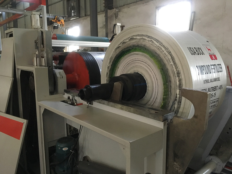
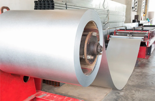
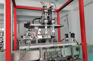
4 Working condition in the site
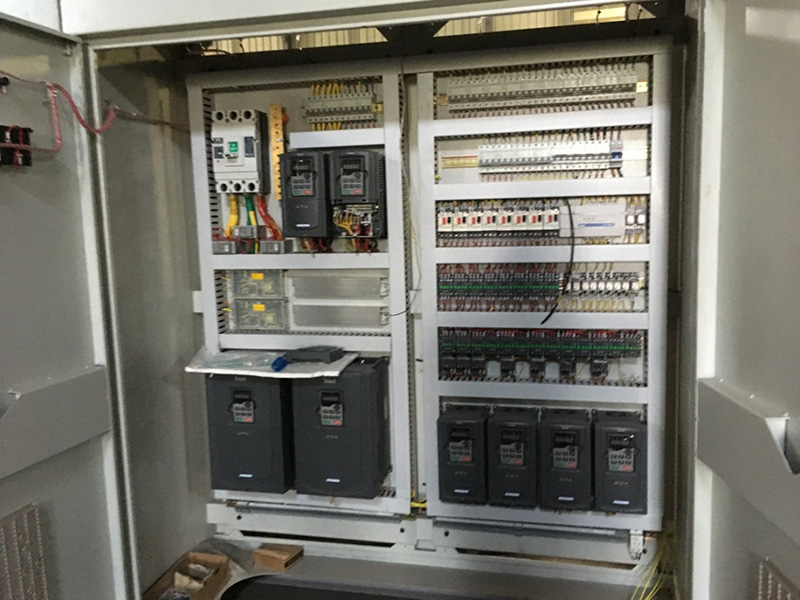
Electric control cabinet
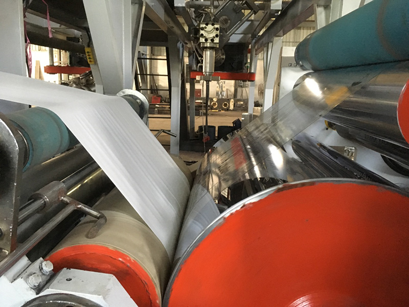
Front cover (not covered with glue)
Cooling roller
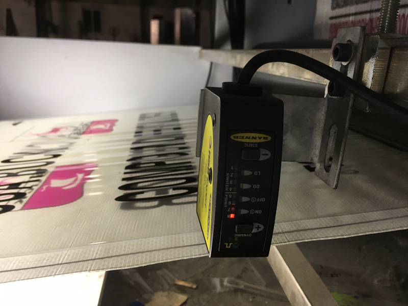
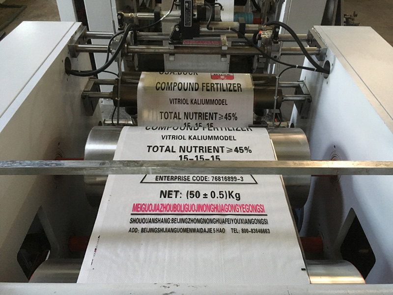
Color mark calibration of Color film
5 System debugging instructions
5.1 Equipment debugging steps
In the scheme of the electric control system, the debugging steps have been completed in the human-machine interface, and the specific debugging step interface is as follows:
The first step is to set the linear speed synchronously. After the wiring is completed according to the system drawing, run in empty load mode in linkage mode without material. Test the linear speed of laminating 2, clamping 1 and cooling stations. If the linear speed is not synchronized, fine adjustment can be made through the touch screen synchronous correction interface.
The second step is to set the mechanical parameters. Firstly, the color mark sensor is applied to the color mark to determine whether the two color mark signals are normal; secondly, according to the actual situation, the parameters such as color film spacing, drum diameter, color mark detection window width and other parameters are set to ensure that the system is calibrated according to the calibration range to avoid wrong calibration; finally, the maximum window and minimum window of calibration are adjusted to ensure that the system automatically filters out the miscellaneous color mark.
The third step is to calibrate the color mark position. In the pilot production of color film, first, observe the detection status of clamping 1 and clamping 2 color marks in the touch screen color mark calibration function setting interface. Under normal circumstances, it will show that the calibration is successful. If the display of calibration is not successful, please check whether the color mark sensor and color mark wiring as well as the maximum / minimum color mark width are appropriate; secondly, observe the clamping 1 and clamping 2 color mark windows in this interface, and according to the measured color mark, the maximum and minimum detection windows of color mark should be adjusted appropriately to avoid unsuccessful calibration due to improper setting of parameters. Finally, the actual production color standard deviation is measured and the color mark offset of the benchmarking interface is adjusted to make the calibration accurate.
The fourth step is to set up the normal production. After color mark calibration, the production test can be carried out normally, and the change of production efficiency can be adjusted by adjusting the production speed. When the feedback "current production speed" is less than the set production speed, please confirm whether the production speed of the main engine has reached 1500 rpm. If so, it indicates that the line speed enters the speed limit mode.
Note: the system has the function of formula recording / calling out. For the materials that have been stably produced, the current production parameters can be stored in the corresponding formula number in the touch screen through the "current formula storage" function of the touch screen interface. If the material is to be produced next time, directly use the "current formula writing" function of the touch screen interface to call out the parameters of the previous stable production, which further reduces the difficulty of system debugging.
5.2 Equipment coating effect
The results showed that the effect of this system was as follows
Linear speed synchronization: the linear speed adjustment range is 10 ~ 170m / min, the whole speed section is continuously adjustable, the swing error of tension floating roller in the full speed regulation section is + 0.5%, and the linear speed error of each station section is + 0.1m/min.
Production speed: 10 ~ 170m / min, the whole speed range is continuously adjustable, the adjustment accuracy is 0.1m/min, the benchmarking effect is stable, and there is no deviation with the increase of production speed.
Color mark offset: the accuracy of front and reverse color mark deviation is + 5mm (bag length is about 1000mm).
Miscellaneous color mark filtering: the miscellaneous color mark signal has no effect on the accuracy of color mark tracking
Broken film condition: the reverse tightening length is set according to the deformation of color film, which can completely avoid the broken film.
Debugging speed: for new materials, the color mark offset is normal, which can achieve one-time compensation; for old materials, the parameters can be directly exported through the formula function, without repeated debugging.
6 Conclusion
The film machine system electronic control solution uses a set of INVT electronic control equipment including touch screen, PLC, inverter and servo motor, which perfectly replaces the system solution of imported brand Yaskawa inverter and Siemens PLC. At the same time, the optimized color mark processing scheme also ensures that the system has faster tracking speed, more accurate color mark filtering, faster production speed and more efficient debugging method than the imported brand scheme. The cost-effective system solution of INVT on the film coating machine enhances the competitiveness of equipment manufacturers, and also reflects the strong system integration ability of INVT.
Reference
[1] 《Goodrive35 Inverter Product Manual》 Shenzhen INVT Electric Co., Ltd.
[2 《IVC Series PLC Programming Manual》 Shenzhen INVT Electric Co., Ltd.
[3] 《VK Series HMI manual》 Shenzhen INVT Electric Co., Ltd.


Our site uses cookies to provide you with a better onsite experience. By continuing to browse the site you are agreeing to our use of cookies in accordance with our Cookie Policy.


 Share
Share
 Facebook
 Twitter
 Google+
 LinkedIn
 Return list