Abstract: This is a fully automatic folding box assembly machine. The folding box is a patented design product. The position of the sticking board is different from that of the traditional one. At present 6 optical eyes sensors are used to locate the three sides of collection folding box, and five servo axes of the conveyor belt and the front and back plates positioning are used in the way of calculating the coordinated by PLC. The whole system adopts CANopen bus to achieve the effect of high progress and high corresponding speed. Meet the requirements of positioning accuracy +-0.3mm, and the production speed is up to 11 pieces/min.
Keywords: IVC3 PLC, DA200, VS HMI, CANopen
1.Preface
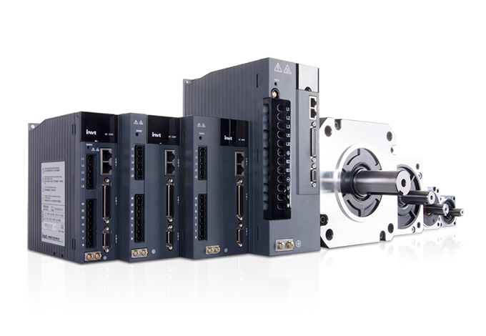
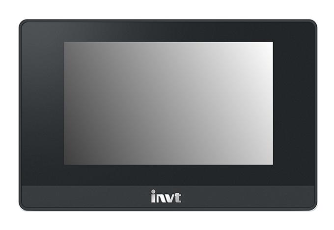
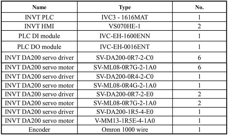
Automatic folding machine adopts INVT IVC3 PLC and 10 pcs of DA200 servo system (7 CANopen type drivers and 3 pulse type drivers). Three channels of high speed outputs of IVC3 are used, and two of them control the X and Y axis of spray adhesive part to work with interpolation action so that the adhesive outlet becomes sensitive and adhesive injection path can be customized. Another pulse output controls conveyor axis, and there are two photoelectricity sensor installed for the interpolation signals. PLC can accurately get the feedback position of current conveyor from encoder so that the deviation is less than 0.1mm. The system uses 2 pcs of VS HMI, one is connected with PLC via RS232, and another is connected with PLC via RS485 so that they can control the assembly machine in two different places.
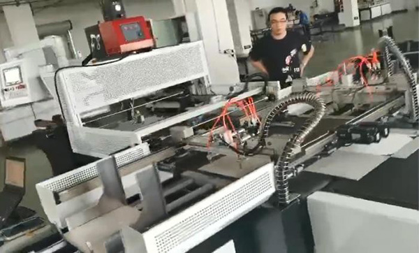
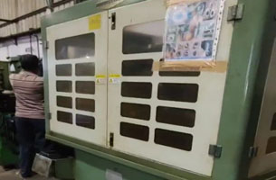
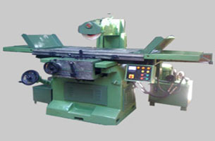
Automatic folding box assembly machine
2. Electrical transmmision system characteristics of automatic folding box assembly machine
2.1 Spray adhesive station
The spray adhesive station is composed of automatic lifting paper platform and spraying X/Y axis.
Automatic lifting paper platform function: It elevates the paper to the height parallel to the optical eyes sensor with the use of a common motor.
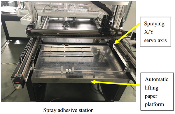
Adhesive injection function: With the use of interpolation function of IVC3, X/Y axis can move in straight line or circular motion. The motion path is defined by 30 motion nodes defined by the customer up to 15 motion paths, to achieve the customer arbitrary definition of spray graphics.
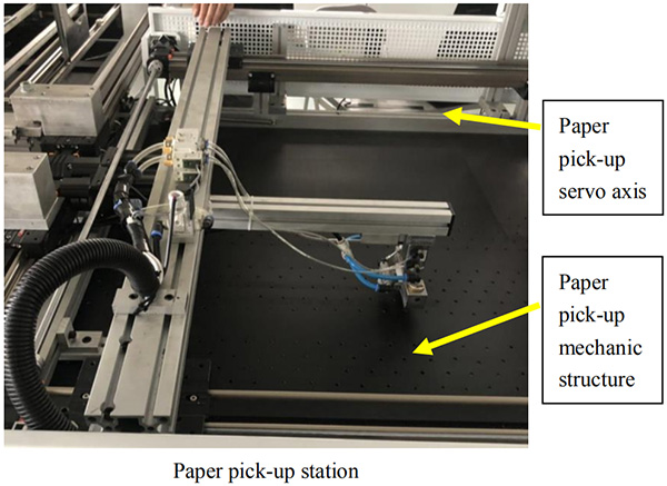
2.2 Paper pick-up station
Paper pick-up station function: pick up the paper after spraying to the conveyor axis. The blow valve and warped paper cylinder are added to avoid the moving of the bottom paper.
2.3 Conveyor station
Conveyor station function: Convey the paper to the assembly position and slowly pass the positioning optical eyes sensor of two side, and then PLC catches the feedback position from encoder to make sure the location of the plate is totally without deviation.
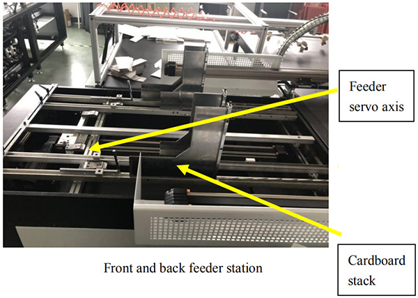
2.4 Front and back feeder station
Front and back feeder station function: Push the cardboard to be assembled to pick-up position and wait for pick-up.
2.5 Front and back cardboard releasing station
Front and back cardboard releasing station function: Cardboard releasing servo axis 1 and axis 2 consist of the gantry front and back action for the cardboard releasing. Servo drive gets the feedback signal from optical eyes sensor and transmit to PLC via CANopen communication, after the calculation of PLC, PLC sends 2 different positions to servo axis.

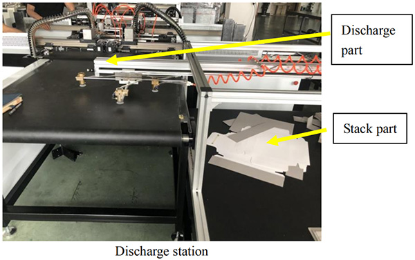
2.6 Discharge station
Discharge station function: Stack the finished poduct in the push area.
3.System control implementation
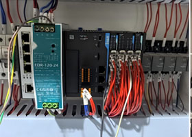
3.1 System configuration
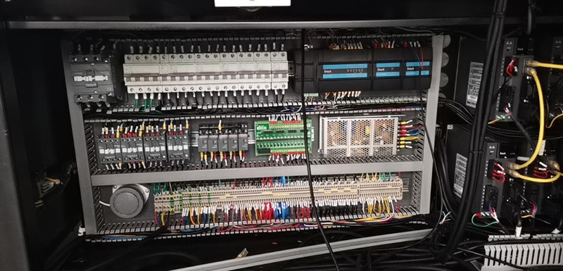
Electrical cabinets figure
3.2 Servo parameters setting

3.3 PLC configuration
1.Modbus protocol: select 115200 baud rate because the communication data volume of HMI is large and there is no big interference at the site.
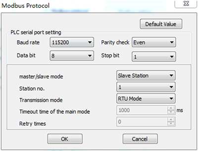
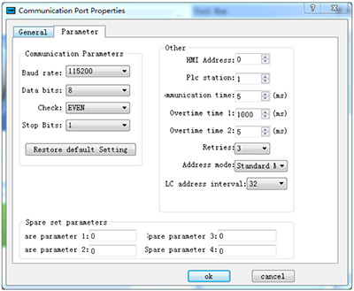
Serial port configuration
2.CANopen configuration: Master station address sets 63, and baud rate is 500kpbs as shown in figure 1. Slave stations set 1、2、5、6、7、8、9 as shown in figure 2.
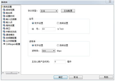
Figure 1. master station configuration
Each servo axis is configured with the same receive send object. All asynchronous communication is adopted. The measured synchronous communication will take up a lot of communication bandwidth and lead to too long communication cycle.
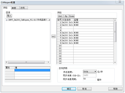
Figure 2. slave station configuration
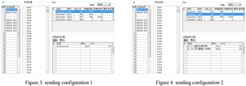
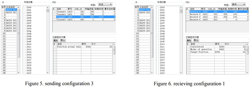
Servo sending objects are: servo state word, servo capture position and servo switch input state. These three status words are asynchronous uninhibited time, which can provide real-time feedback without delay. 100ms suppression time is set due to the frequent updated of servo current location. Figure 3/ figure 4/ figure 5
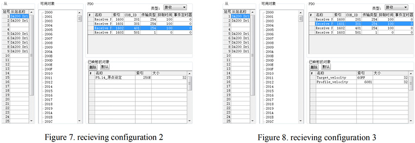
Servo receiving objects include: control word, control mode, target position, target speed (speed mode), target speed (position mode), origin setting. Asynchronous 10ms suppression time was used. Figure 6/ figure 7/ figure 8.
3.4 HMI configuration
Set baud rate, data bits, check and stop bits corresponding with the settings in PLC.
5.Ending
The equipment adopts the CANopen bus to simplify the servo wiring, compared with the pulse mode an IVC3 small PLC can control 10 servo to execute high speed operation. The servo encoder capture function is used to grasp the position of the servo when it receives the optical eye signal to improve the capture accuracy and servo running speed, which makes positioning accuracy within +-0.3mm and increases the production speed to 11 pieces per minute.
Reference documentation
[1]《IVC Series small PLC programming manual V1.4》
[2]《DA200 High performance AC servo driver manual V2.2》
[3]《DA200 AC servo driver CANopen manual》


Our site uses cookies to provide you with a better onsite experience. By continuing to browse the site you are agreeing to our use of cookies in accordance with our Cookie Policy.


 Share
Share
 Facebook
 Twitter
 Google+
 LinkedIn
 Return list