Abstract: According to motor production standards, after the AC motor is produced, motor performance and characteristics tests are required. Connect two motors with suitable power coaxially to conduct the motor towing test. The test bench can measure the motor's voltage, current, output torque, speed, input and output power, efficiency, and other performance parameters, and draw various performance curves according to the measured data.
Keywords: GD800, electric motor test bench, AFE, common DC bus, 4 quadrant
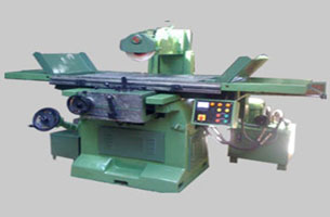
1.Electric motor test bench system introduction
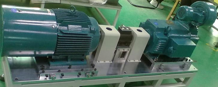
The electric motor test bench includes 2 motors, one is MUT (Motor under test), the other is DM (Driving motor). During the test, the controller controls the motor speed and torque. One motor works under motoring mode, the other motor works under generator mode. The system can realize features:
a.Motor durability and mechanical properties
b.Motor temperature rise and overload performance
c.Motor field weakening performance and efficiency, power factor
d.Display voltage, current, torque, speed, output power, and efficiency in real time
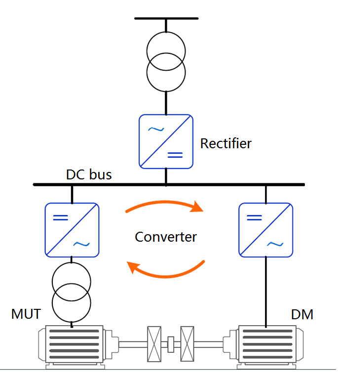
Figure 1: Motor test bench system:
Generally, there are 2 ways for testing:
a.Speed mode: firstly make 2 motors run the same direction and keep the running frequency are the same. Then reduce the DM speed, because 2 motors are coaxial, the real running speed are the same, so the DM rotating magnetic field speed is lower than actual rotor speed, motor works under regenerative mode, output reverse torque, this can add the load for MUT, and MUT output current will increase.
b.Torque mode: DM driver set as torque control mode, after 2 motors start, controller sends the DM torque signal as negative torque, this way can also add load for MUT.
2.Electric motor test bench project
a.MUT voltage needs 2 kinds: 400v/690v.
b.MUT max. power rating is 315kW, also support 160kW/75kW/11kW.
c.MUT includes normal motor and frequency motor
d.DM motor includes 500V: 315/160/75/11kW.
Motor test bench system introduction:
a.Power input is 380Vac, GD800-96 PWM Rectifier support to increase the DC voltage, to support 500V DM motor.
b.If the MUT is not frequency motor, enable sinewave filter.
c.600kVA transformer is used for increasing votlage when MUT is under block mode
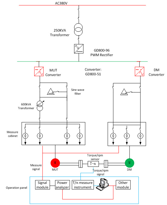
Figure 3: Motor test bench system introduction
3.VFD selection for motor test bench project
a.Power unit
To make sure the motor constant torque output, keep DC bus voltage stable, and reduce the interference in the site, select the GD800-96 AFE (Active front End) as rectifier, GD800-96 PWM rectifier adopts IGBT to replace diode rectifier, comes standard with LCL filter, input THDi<5%.
When the motor test bench is working, one motor is under motoring mode, the other is regenerative mode, so can select small power rating rectifier: 500V 250kW GD800-96 rectifier.
Converter adopts 2pcs 500v 400kW GD800-51 power unit, output frequency range is 0~400Hz, frequency resolution is 0.01Hz, open loop torque response time is less than 20ms.
b.Control unit
The rectifier control unit (RCU) and inverter control unit (ICU), adopt optical fiber connection, avoid the interference. RCU and ICU come standard with RS485 interface, communicate with controller adopt Modbus/RTU protocol. The controller can send speed/torque signal to RCU/ICU by communication, low cost and high efficiency.
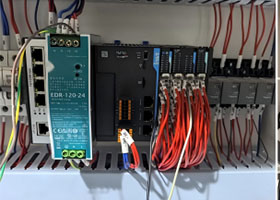
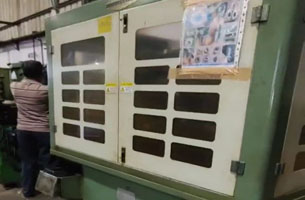
4.Photos in the site
The controller and motor test bench photos in the site
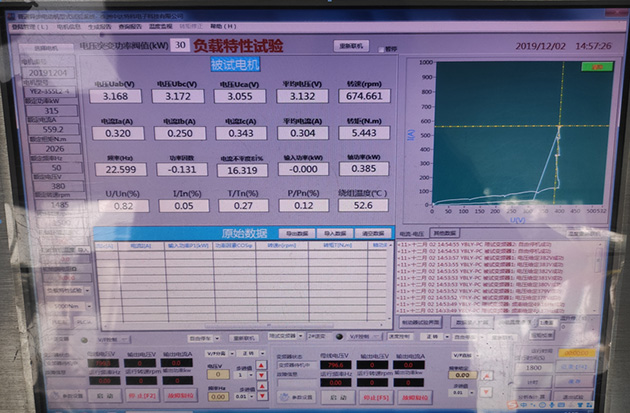
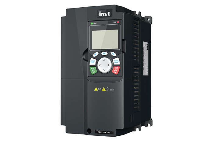
Figure 4: Operation panel
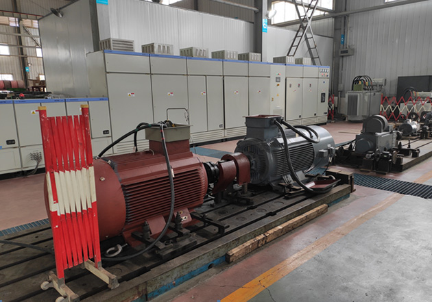
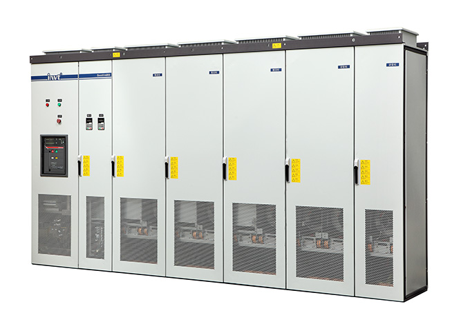
Figure 5: Motor test bench
5.Summary
In the field of motor testing, 2 motors adopt DC common bus is a simple and efficient solution, to form a closed energy internal circulation channel it can reduce the rectifier capacity, even ordinary factories can build such a simple test platform. However, in the professional motor production factory, a series of long-term test items are required. There are many test instruments, different sensors, transmitters, and precision instruments that require high control accuracy, EMC performance, and stable reliability of the entire system. AFE active feedback rectification without harmonic pollution problem, which ensures that the DC bus voltage is constant and adjustable while also ensure stability and reliability.
About converter, the system also can adopt INVT GD350 series vfd drive, GD350 also supports DC common bus and multi communication protocol, and different encoder.
Reference:
1. GD800 hardware operation manual. Shenzhen INVT Electric Co., Ltd.
2. GD800-96 operation manual. Shenzhen INVT Electric Co., Ltd.


Our site uses cookies to provide you with a better onsite experience. By continuing to browse the site you are agreeing to our use of cookies in accordance with our Cookie Policy.


 Share
Share
 Facebook
 Twitter
 Google+
 LinkedIn
 Return list