Item | Specifications | |
Power input | Input voltage | Rated voltage: AC 380V (Available voltage classes: 220, 380, 400, 415, 440, which can be set through the function code) Allowed input working voltage range: AC 1PH 220V(-15%)–240V(+10%) AC 3PH 380V(-15%)–440V(+10%) |
| Input frequency | 50Hz or 60Hz; Allowed range: 47–63Hz | |
Power output | Output voltage (V) | 0–Input voltage (V) |
| Output frequency (Hz) | 0–400Hz | |
Technical control | Control mode | V/F, sensorless vector control, closed-loop vector control |
| Motor type | Asynchronous motor and permanent magnet synchronous motor | |
| Speed ratio | For open-loop vector control: 1:200 For closed-loop vector control: 1:1500 | |
| Speed control accuracy | ± 0.5% (open-loop vector); ± 0.05% (closed-loop vector) | |
| Speed fluctuation | ± 0.3% (sensorless vector control) | |
| Torque response | < 20ms (sensorless vector control) | |
| Torque control accuracy | 10% (sensorless vector control) | |
| Starting torque | For asynchronous motor sensorless vector control: 0.3Hz/150% For sensor-included vector control: 0 Hz/200% | |
| Overload capacity | 150% of rated current: 1 minute 180% of rated current: 10 seconds 200% of rated current: 1 second | |
Running control | Frequency setting method | Digital setting, analog setting, multi-step speed running setting, and Modbus communication setting, implementing switching between channels |
| Voltage auto-adjustment | Used to keep constant voltage automatically when the grid voltage transients | |
| Fault protection | Used to provide more than 30 fault protection functions against faults such as overcurrent, overvoltage, undervoltage, overheating, phase loss and overload | |
Peripheral interface | Analog input | 1 input (AI1): 0–10V/0–20mA Resolution: ≤20mV |
| Analog output | 1 output (AO1): 0–10V/0–20mA Resolution: ≤20mV | |
| Digital input | 8 common inputs; Max. frequency: 1kHz; internal impedance: 3.3kΩ 1 high speed input; Max. frequency: 50kHz Resolution: ≤2ms | |
| Digital output | 1 terminal Y for open collector output | |
| Relay output | 3 NO programmable relay outputs RO1A NO, RO1C common terminal RO2A NO, RO2C common terminal RO3A NO, RO3C common terminal Contactor capability: 3A/AC250V, 1A/DC30V | |
| Power output | Used to provide 24V/200mA and 10V/50mA power output | |
| PG expansion card (optional) | Incremental 5–24V; sine and cosine; absolute value; UVW | |
| IO expansion cards (optional) | 3 common digital inputs 1 analog input AI2 1 NO/NC relay output 1 HDO output 1 Y output 1 RS485 interface (supporting RTU) 1 CAN communication interface | |
| STO expansion card (optional) | Used to provide STO security terminal functions | |
| Bluetooth/Ethernet expansion card (optional) | Used for equipment commissioning through Bluetooth or Ethernet communication | |
Others | Mounting method | Wall mounting |
| Running environment temperature | -10–50˚C. The VFD must be derated if temperature is above 40˚C. | |
| MTBF | 100,000 hours | |
| Ingress protection (IP) rating | IP20 | |
| Cooling method | Forced air cooling | |
| Braking unit | Built in VFD models ≤15kW; optional for other models | |
| DC reactor | DC reactors are standard configuration for VFD models ≥18.5kW. | |
| EMC filter | Optional filters C2 can be configured, meeting IEC 618000-3 C2 requirements. | |
Popular Searches:

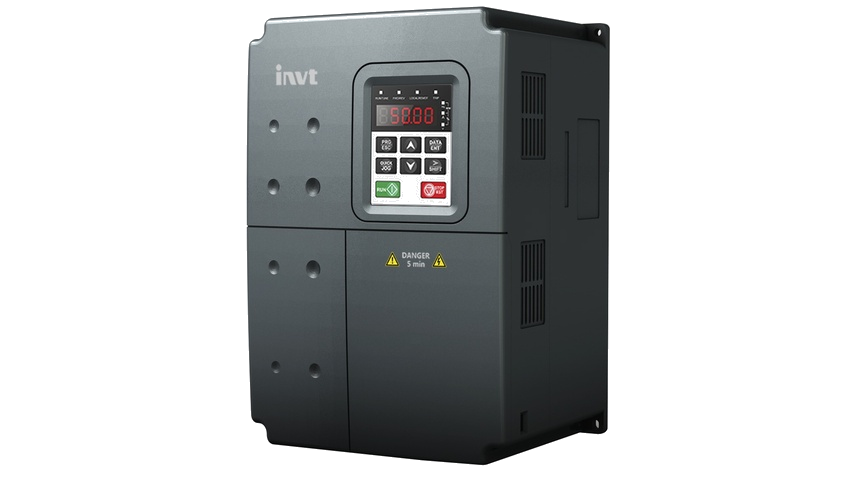
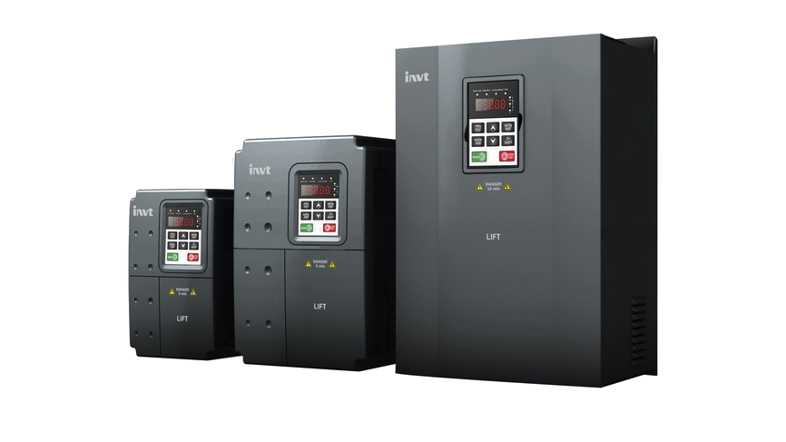
GD300L Series Lift-Dedicated VFD
Goodrive300L series lift-dedicated VFDs are the new-generation elevator VFD that INVT uses Goodrive300 control platform to develop based on CHV180 series VFD. As using TI 28-series DSP and advanced vector control technology, Goodrive300L series VFD gain great achievements in security and reliability, control performance, and use functions.
·1.5-30kW
·
Voltage auto-adjustment
·
IP20 protection level


 Images
Overview
Features
Specifications
Downloads
More Resources
Case
Videos
More
Features

Safe and Reliable
 Support optional Built-in Safety Torque Off
function, and passed the certification of SIL 3, EN/ISO 13849-1, EN954-1, and etc.Forced deceleration prevent the lift from soaring to the top or diving to the bottom during the upward or downward running.Brake and contactor control can control the contactor and brake based on lift running logic, enhancing lift safety performance.UPS and auxiliary battery provide reliable power supply during power failure.
01
comfor
Starting torque compensation with weight
sensors prevent reverse slip at startup by parameter setting, ensuring stable lift startup.Starting torque compensation without weight sensors implement precise control on the gearless synchronous-tractor lifts, achieving stable startup and improving comfort.Optimized ASR use variable proportional and integral gain control, providing quick dynamic response in startup and stop states and improving comfort during constant-speed running. ACC/DEC S curve algorithm improve comfort during motor ACC, DEC, and stop02
Ease of use
Ability to drive asynchronous and
synchronous motorsStatic identification on the initial pole angle of a synchronous motor execute autotuning for the permanent magnetic synchronous motor in static mode without unloading, simplifying commissioning.Support of multiple types of encoder: incremental, sine-cosine, absolute, and UVM encoders.Energy-saving running mode support the use of RBU, implementing energy-saving running.03
Specifications
Downloads
By Type:
 Load More
Have questions or need support?
Our professional team is here to help.


Inquiry
TOP
Popular Searches:
Repair Progress Tracking | Identity Verification
To protect your repair information, please verify using the mobile number reserved on the service order.
Verify with the reserved mobile number
Verify
SMS Verification Code *
If you cannot receive the code, please contact the after-sales hotline. 400-700-9997


Contact INVT
Get in touch with INVT. Our team will get back to you shortly.
Full Name *
Company Name *
Email Address *
Phone Number *
Country *
City
Inquiry Type *
Product Category *
Select the product you're interested in.
-
Industrial Automation
-
Network Power
-
PV & ESS
-
e-Mobility
Your Message / Requirements *
I have read and agree to INVT Privacy Policy and Terms of Use
Captcha *