Popular Searches:

Q : Common issues with UPS sampling resistor circuit malfunctions


A: The UPS will report ‘Bypass Volt Detect Fail-Set’ fault (as shown in Figure 3 below).
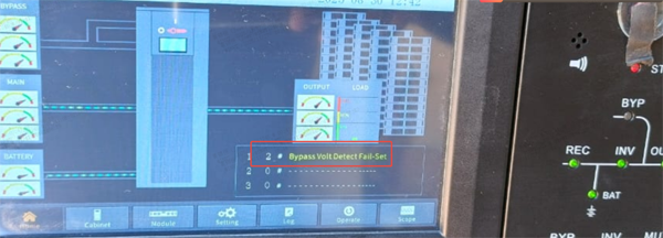
Figure 3
NOTE: The Figure shows '2# Bypass Volt Detect Fail-Set' fault, where 2# refers to module 2 and 0# to the bypass module.
Q3: When the UPS reports ‘Bypass Volt Detect Fail-Set’ fault, what are the typical troubleshooting steps?
A: When the sampling resistor circuit is faulty, the typical troubleshooting steps are as follows:
1. Check the actual input/output values of the circuit based on the location of the fault;
2. If the actual input/output values are normal, consider whether the detection circuit on the PCB board is faulty; (For modular UPS systems, first determine if the power module/bypass module detection circuit is faulty)
Q4: How to detect whether the sampling resistor circuit on the PCB board is faulty?
A: The method for detecting a sampling resistor circuit fault is as follows:
1. Locate the corresponding point on the PCB board; use the ohmmeter function (Ω) of a multimeter; touch the two points on the PCB board by the multimeter probes; check whether the resistance value is within the effective range (the deviations of resistance value will vary depending on the type of resistor) ; (The detection points are shown in Figure 4).
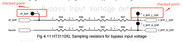 Figure 4
More Resources

Services
Learn about INVT’s global after-sales policies, service processes, and technical support commitment.
Learn More

Downloads
Get product catalogs, manuals, drawings, software, certificates, and more.
Download Now

Training Videos
Learn product knowledge, operation guides, and application technologies through online training videos.
Learn More


Inquiry
TOP
Popular Searches:
Repair Progress Tracking | Identity Verification
To protect your repair information, please verify using the mobile number reserved on the service order.
Verify with the reserved mobile number
Verify
SMS Verification Code *
If you cannot receive the code, please contact the after-sales hotline. 400-700-9997


Contact INVT
Get in touch with INVT. Our team will get back to you shortly.
Full Name *
Company Name *
Email Address *
Phone Number *
Country *
City
Inquiry Type *
Product Category *
Select the product you're interested in.
-
Industrial Automation
-
Network Power
-
PV & ESS
-
e-Mobility
Your Message / Requirements *
I have read and agree to INVT Privacy Policy and Terms of Use
Captcha *