Abstract: This is an Etching & Ultrasonic cleaning industry. Here the Fecl3 & DI water are used to do the Etching and Ultrasonic cleaning Process. Earlier customer were used normal manual valves to control the Chemical and water. Now we are done fully automated Vale open close and Pressure based pumping system.
Keywords: TS621 PLC, GD200A, VS-HS HMI
Project background:
i) Etching:
Chemical etching is a method of engraving that uses a high-pressure high-temperature chemical spray to remove material to create a permanent etched image in metal. A mask or resist is applied to the surface of the material and is selectively removed, exposing the metal, to create the desired image.
Metallographic etching encompasses all processes used to revel particular structural characteristics of a metal that are not evident in the as-polished condition. Examination of a properly polished specimen before etching may reveal structural aspects such as porosity, cracks, and nonmetallic inclusions.
Step-by-Step Metal Chemical Etching Process:
• Step 1: Creating the Design. ...
• Step 2: Selecting and Preparing the Metal. ...
• Step 3: Preparing the Metal for Photo Etching (Photoresist Coating) ...
• Step 4: Exposing the Metal to UV Light. ...
• Step 5: Developing. ...
• Step 6: Metal Chemical Etching. ...
• Step 7: Stripping the Photoresist.
ii)Ultrasonic cleaning:
Ultrasonic cleaning in industry is a method that uses high-frequency sound waves to agitate a liquid and remove contaminants from objects, even in hard-to-reach areas. This process, known as cavitation, generates microscopic bubbles that implode upon contact with the object's surface, dislodging dirt, grease, and other debris.
Industrial ultrasonic tanks are commonly used in the automotive, aerospace, medical device and semiconductor industries. They can be used to clean a wide variety of objects, including engine parts, machinery components, medical implants, musical instruments, firearms, electrical circuit boards, and much more.
Challenges & Solutions:
i) One common pump will supply the water for all 3 units. So we have to maintain the water pressure if any one the system is running.
ii) All three systems should be run with interlinked. Any one of the system is tripped, alarm should show for all 3 system.
iii) Variable setting pressure required for water and chemical control. Also VFD should run PID basis.
iv) Control the valve based on the setting litters for both water and chemical for Etching system.
Water and chemical pressure controlling done by PID basis. Valve open close control done by using the flow meter feedback. So set litter achieved. All 3 System PLC are linked with Modbus TCP/IP communication. So that we can monitor and control easily for all system also alarm and trip will indicate for all screens.
Introduction


MACHINE PROCEDURE:-
This project has two different systems: Etching system and Ultrasonic cleaning system.
1) Etching system:
A. Fecl3 and DI water Pump & Pressure based PID pumping system: Fecl3 chemical will use to Etching process and DI water will use to cleaning the materials after etching. Large quantity of Fecl3 and DI water will stored in to the storage tank. Stored Chemical and water will feed by using the feed pumps. This system have totally 4 feed pumps. 2 no’s of feed pumps for Fecl3 and 2no’s of feed pumps for DI water.
These feed pumps are connected to our GD200A VFD and this Pumping line connected with pressure transmitters. So whenever the system runs feed pump will pump the chemical and water based on the pressure settings by PID control. It will maintain the set pressure always.
B. Motorised Valve: Both Fecl3 and DI lines are have individual motorized control valve. This valve will control by 4-20ma analog input. Entire system flow will control by this motorized valve. Also this motorized valve open level can be set in HMI.
C. Etching machine, Flowmeter & its control valves: Totally this unit have 12no’s of pre-etching and etching machines. Each machine will connected with one Fecl3 line and one DI water line. Each lines have one motorised valve for its flow control. Each machine will have 50 litter tank on its bottom. When the customer need water or Fecl3 they will set the required litter of DI or Fecl3 in HMI and engineer will turn ON its motorized valve. Then Machine motorized valve will open and fill the machine tank.
Once the actual flow will reaches in to the set level machine motorized valve will close. So required litter fill in the tank. Both Fecl3 and DI water will have each Flow meter and its flow feedback monitor by PLC. Based on the flow feedback will control the machine valve.
2) Ultrasonic cleaning system:
Plant have 2 individual ultrasonic cleaning system. Each system have one main motorized valve and 12 no’s of ultrasonic cleaning tank and each have individual motorized valves for control the DI water.
A. Main Motorized valve: This valve will used to control the overall flow of the system. This will control by 4-20ma output from the PLC. Valve open level can set in HMI. Both system will have individual motorized valves.
B. Individual Motorized valves: Each system will have 12 no’s of ultrasonic cleaning units. Each ultrasonic cleaning tank will have individual motorized valves for control function. This control valves have inbuilt litter setting meter. So engineer can set the required litter in the inbuilt meter. When the engineer will give an open command, Valve meter will give an input to the PLC. Based on that input feedback PLC will turn ON (OPEN) the specific motorized valve. Once the set litter has reached, built in meter again give one feedback to the PLC. Based on the feedback PLC will turn OFF (CLOSE) the motorized valve.
C. Common Flow meter: Both ultrasonic system will have one common flow meter which is used to measure the overall flow to the ultrasonic systems. It will monitor in HMI in terms of litter^3/hour.
D. Synchronised operation: In this project have totally 3 different systems. 1) Etching 2) Ultrasonic cleaning-1 & 2. All PLC are connected with Modbus TCP IP Communication. Also feed pumps are also common. So if any trip or error happen on the DI feed pump system, all PLC will stop its operation and will show the relevant error or alarm message on HMI screens.
Project information and Solution
1. Project information
Site information: Ohimium industry-Chengalpattu.

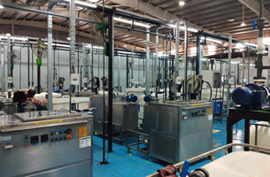
(i)Etching system machine photo

(ii) Ultrasonic cleaning system – 1

(iii) Ultrasonic cleaning system – 2
2. INVT solution
Product | Model no. | Qty | Application |
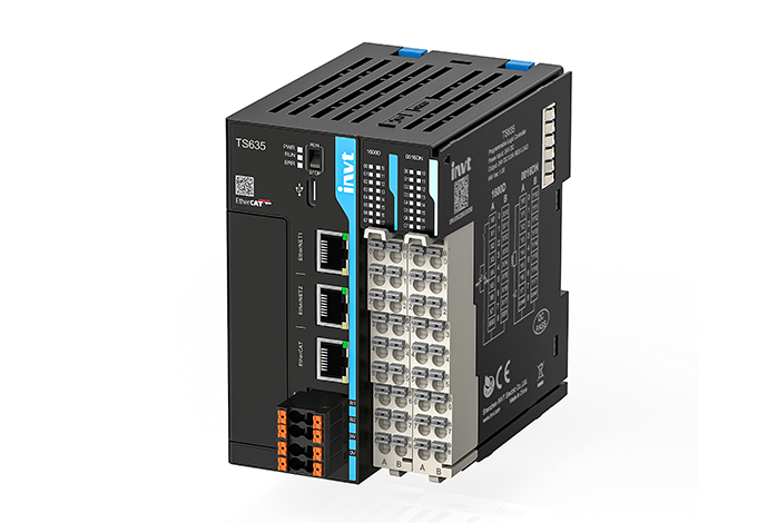
PLC | TS621 | 3 | CONTROLLER |
FLEX IO | 1600D 0016DN 4AD 4DA | 3 5 4 3 | CONTROLLER |
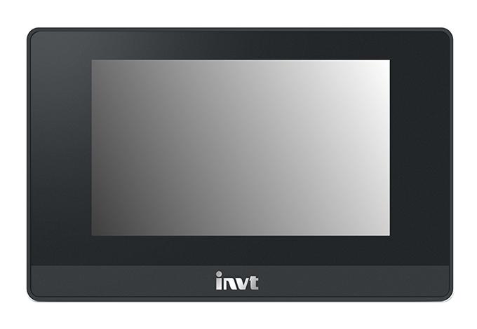
HMI | VS070HS | 3 | CONTROLLER |
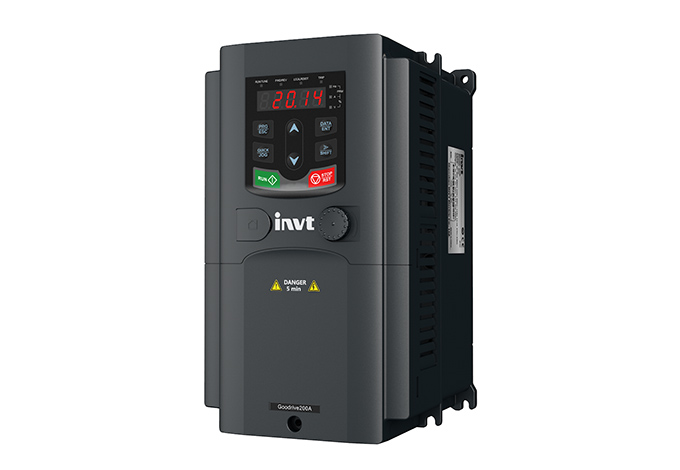
INVERTER | 2.2 KW | 2 | FEED PUMP |
3. System Configuration:

System commissioning

Control panels (Etching system)

Control panels (Ultrasonic cleaning system - 1)

Electrical panel (Ultrasonic cleaning system – 2)
Advantages and benefits
• Easy and simple to operate.
• Chemical and water level can be settable. So we can avoid the overflow and will do the process with correct mixing ratio.
• Reduce the Processing time.
• Monitor the overall flow and we can control the flow.
Conclusion
Easy to operate the machine and can easy to maintain the system. Increase the production also quality of the products.


Our site uses cookies to provide you with a better onsite experience. By continuing to browse the site you are agreeing to our use of cookies in accordance with our Cookie Policy.


 Share
Share
 Facebook
 Twitter
 Google+
 LinkedIn
 Return list