Summary:Slitting machine rewinding is the paper rolls by rewinding and Slitting,make the different width of the single layer of paper to multilayer and Slitting into various width of paper towel semi-finished products at the same time, It is the device to the next process raw produce. As the following is the example to show you the invt Goodrive35 inverters applications in the 1200 meters Rewinding and Slitting machine.
Keywords: Invt inverters. Goodrive35. Rewinding and Slitting machine
I.Introduction:
The 1200 m rewinding and Slitting machine structure is divided into front winding, rear rewinding, bottom knife roll calendar, under pressure light roller, (some models according to customer requirements embossing top and bottom roller), the rear frame 1, lead roller rear rack 1, rear frame 2, frame lead rollers 2, rear rack 3, rear rack lead roller 3, the rear frame 4 lead rollers…, it can increase or decrease the numbers of the rear racks according to the customers’ requirements. The work processes is rear rack lead rollers flatten unwinding raw materials paper to calendaring or embossed composite multilayer paper - cut - after winding down to a certain desired diameter under paper - to the next process.
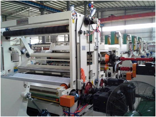
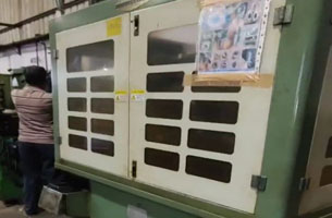
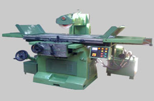
Mechanical picture:
II.1200 meters rewinding and minute Slitting machine process requirements
Since 1200 m rewinding Slitting machine speed faster, so the mechanical aspects of each work roller dynamic balance requirements of high precision prevent dithering and produce parts in mechanical operation metal fatigue accidents, so only few domestic manufacturers can do it, there is currently the domestic first the fastest rewinding Slitting machine.
in the winding part of the winding roll before and after the winding roller with independent motor driven by base paper and upper and lower the winding roller friction winding base paper, paper is also a rack through belt friction rolling, rolling is the feature of this does not need complex coil diameter calculation, as long as the guarantee of winding and rolling linear velocity at high speed and low speed linear velocity can guarantee the same ratio of paper tension is the same, this need each motor speed follow sex between high, or will cause the broken of paper making production can't continue, to wear paper will waste a lot of manpower and time, and waste of raw materials will also increase the cost of production.
Requirements in various parking mode will not broken paper, such as power and stop, stop, and so on.
Ⅲ.the electrical configuration
1,The motor configuration:
| Item | Motor power | Rated voltage | Rated current | Rated speed | Rated frequency |
| front winding machine | 39kw | 350V | 90A | 960 | 50Hz |
| rear winding machine | 39kw | 350V | 90A | 960 | 50Hz |
| Bottom knife roller motor | 11kw | 380V | 3.3A | 1450 | 50Hz |
| upper Calender motor | 39kw | 350V | 90A | 1450 | 50Hz |
| Lower pressure light motor | 39kw | 350V | 90A | 1450 | 50Hz |
| 1# Rear frame motor | 15kw | 380V | 34A | 1450 | 50Hz |
| 1# Rear frame paper guide roller motor | 2.2kw | 380V | 6A | 1450 | 50Hz |
| 2# Rear frame motor | 15kw | 380v | 34A | 1450 | 50Hz |
| 2# Rear frame paper guide roller motor | 2.2kw | 380v | 6A | 1450 | 50Hz |
| 3# Rear frame motor | 15kw | 380v | 34A | 1450 | 50Hz |
| 3# Rear frame paper guide roller motor | 2.2kw | 380v | 6A | 1450 | 50Hz |
| 4#Rear frame motor | 15kw | 380v | 34A | 1450 | 50Hz |
| 4# Rear frame paper guide roller motor | 2.2kw | 380v | 6A | 1450 | 50Hz |
2.The inverter configuration:
| The inverter type | |
| front winding machine | GD35-045G-H1-4F |
| rear winding machine | GD35-045G-H1-4F |
| Bottom knife roller motor | GD35-022G-H1-4F |
| upper Calender motor | GD35-045G-H1-4F |
| Lower pressure light motor | GD35-045G-H1-4F |
| 1# Rear frame motor | GD35-015G-H1-4F |
| 1# Rear frame paper guide roller motor | GD35-04G--H1-4F |
| 2# Rear frame motor | GD35-015G-H1-4F |
| 2# Rear frame paper guide roller motor | GD35-04G-H1-4F |
| 3# Rear frame motor | GD35-015G-H1-4F |
| 3# Rear frame paper guide roller motor | GD35-04G-H1-4F |
| 4#Rear frame motor | GD35-015G-H1-4F |
| 4# Rear frame paper guide roller motor | GD35-04G-H1-4F |
| DBU | DBU100H-320-4 |
Please configure input and output reactors, braking resistor of each drive model. Other accessories such as air switches, contactors, relays configure by mechanical factory.
Ⅳ.Invt Goodrive35-H1 inverter advantages
1, Goodrive35 is a high-performance vector inverter can be widely used for speed Control Method of Asynchronous motors and permanent magnet synchronous motor. Relying on 32 products DSP, a leading international vector control algorithm to achieve high-performance, high-precision motor drive control, improve product reliability and adaptability of the environment at the same time, strengthen the customer's ease of use and industry specialization design, more optimized application more flexible, more stable performance;
2,It can be applied to a variety of motor drives: Vector control for asynchronous motors and permanent magnet synchronous motor , effectively reducing user inventory without considering the motor type compatibility issues, no longer needed for different motors were equipped with
different drive stock;
3, the inverter can set two motor parameters, to drive two different types and power of motor;
4,the exact parameters auto-tuning , can accurately rotating or stationary motor parameters
auto-tuning, easy to debug, simple operation, providing greater control accuracy and speed of response;
5, It can proved 3 types of control: V / F, open-loop control and vector control with PG card, wherein in the case of sudden acceleration load, speed fluctuation is very slight
| Speed ratio | 1:1000 |
| Speed control accuracy | ±0.02% |
| Servo control | Pulse given set, you can positioned anywhere in control |
| Divider output Torque response | <10ms |
| Torque control accuracy | ≤5% |
| Starting torque | 0.00Hz/200% |
| Overload capacity | 150% of rated current for 1 minute, 180% of rated current for 10 seconds, 200% rated current for 1 second |
| Divider output | Encoder pulse divider output (H1, D1-type terminals) |
| Speed / position mode switch | Support Terminal switch |
| Encoder | A1 inverter supports 200kHz, B1, C1 inverter supports 100kHz, D1 inverter supports 500kHz, H1 inverter supports 300kHz |
| Positioning performance | Support Z pulse and photoelectric switch positioned, accurate positioning without overshoot |
1.Adopted the advanced to the three phase modulation method, makes the motor run more smoothly, less noise, compared with the previous control motor noise can be reduced by 20%;
2.In the high-speed spindle, frequency conversion motor, direct driving motor and special motor drive well;
3.Good voltage and current control, effectively reducing the number of times drive failure protection;
4.Offers a variety of braking, quick stop, dynamic braking, DC braking, flux braking;
5.The standard built-in C3 input filter,C2 optional filter;
6.Abundant external interface, pluggable terminal block, saving the user time to replace the field device, reducing field wiring workload: There are 8 digital inputs, one high-speed pulse, three-channel analog input, one digital output, all the way to high-speed pulse output , two analog outputs, two relay outputs;
7.High-performance keyboard, standard external lead-in LED keypad, supports upload and
download parameters, the maximum length of the outer lead 200m, the keyboard comes with a digital potentiometer. Optional external lead-type LCD keyboard, support for uploading and downloading parameters, maximum support ten lines of ten Chinese display, support for multi-lingual display;
8.1.5-30 Kw inverter built-in brake unit
9.Full range of products to support common DC bus program
10.Heavy duty design, 150% of rated load 60s, 200% of rated load 1s.
11.Rich applications, to meet customers' industry-specific requirements: v/f separate ,2 sets of motor parameters, virtual terminal function, speed tracking, digital, high-speed pulse, the relay may delay the opening of the shutdown, battery indicator, stop delay;
12.Product design strictly follow the IEC International Standard, and by the international
certification body TÜV SÜD CE certification testing, the domestic industrial sector only TÜV-MARK signs affixed to the manufacturers, Goodrive300 inverter provides 24 months long warranty period;
13.Complete the reliability of the test system to ensure that products meet the most
complex application environment, the domestic industrial sector only get TÜV SÜD qualification awarded ACT manufacturers
14.Variety of communication; standard MODBUS communications, optional PROFIBUS,
Ethernet communication card;
15.Easy to use PC software
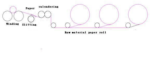
V.1200m rewinder and Slitting machine process flow diagram
1200m rewinder and Slitting machine process as following:Unwinding——Calender
(Embossing)——Slitting——Winding.
VI.1200m rewinder and Slitting machine control solutions
1.Solutions instructions
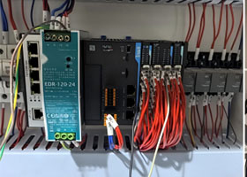
The rear part of the winding inverter is the host, Operating frequency is given by the PLC analog module, and the signal of running is given by the PLC switch.
The front of the winding drive, bottom knife roller drive, calendering drive, rear rack drive, guide roller drive is slave, the signal of running is given by the PLC switch, Wherein the rear frame drive, guide roller drive, the bottom of the knife roller drive are position control, Position signal is controlled by the host inverter output frequency division, The front of the winding drive, bottom knife roll drive, calender drive is closed loop speed control, the speed signal is control by the host drive encoder divider output. Each slave drives' electronic gear ratio are given by the touch screen, the touch screen adjust each section ratio.(Detailed and specific wiring diagram reference manual of INVT GD35).
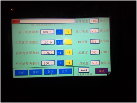
Inverter-site installation images

Ⅶ.Inverters' parameters setting:
4.1 Commissioning procedures:
1.Reset the factory Settings, set the motor parameters, motor parameters auto-tuning;
2.User parameter settings(after set, you can direct factory commissioning)
Do the following for each step:
Inverters'parameters setting(Preparing foR the motors'parameters auto-tuning):
| P02.01 | Motor rate power | Setting according to the parameters of the motor nameplate |
| P02.02 | Motor rate frequency | |
| P02.03 | Motor rate speed | |
| P02.4 | Motor rate voltage | |
| P02.05 | Motor rate current |
Motor parameters auto-tuning:
| P00.15 | 2 | Static auto-tuning (if think about the safety, prohibit motor rotates, the parameter should be set to 2, that is, static auto-tuning) |
After set P00.15 to 2, sure you can RUN under the condition of safety, according to a "RUN" button on the keyboard, the motor start automatic auto-tuning, upon it finish the keyboard display "END", since the study is complete.
Parameters copy:
Through parameter copy, frequency converter parameters can be downloaded to the keyboard, and then the parameters of the keyboard inside directly downloaded to the other two rack frame inverters, The steps are as follows:
1.After set the above parameters, please set P07.01=1,keypad will show “UP”;
2.After copy finish, Insert the keyboard into the second frequency converter and set P07.01=2,keypad will show "DOWN";
3.Successively to complete the three inverter parameter copy by this method
4.Pay attention to in the process of parameter copy, whether the frequency converter drive motor power and stored on the keyboard of the original motor power are the same, such as the motor power is not the same with the P07.01 download function parameter is set to 3, do not download the motor parameters, otherwise can't copy.
4.1.1 The factory debugging.
1.Set each inverter communication address: General PLC communication addresses is 01, the rear winding drive communication addresses is 02, the front of the winding drive is 03, the guide roller is 04, the lower the calender is 05, the upper pressure light is 06, the first rear frame is 07, the second rear frame is 08, the third rear rack is 09,1 # guide rollers is 10,2# guide rollers is 11,the 3 # guide rollers is 12. (Specific address configuration decisions based on the client system)
2.After set the electronic gear ratios of each rear frame on the touch screen and press the OK button, then observation of the actual values are not changed, and the set value is the same, then the communication is no problem.
3.Test start production of each action is correct, the tightness of the system debugging
paper valid explanation, no problem, you can put in storage, commissioning is completed.
Ⅷ.Using Conclusion:
After boot test run for a period of time, the system is stable and reliable. can save a lot of manufacturing costs than the previous Siemens control scheme , The Siemens full servo control scheme of the system needs to be more than 60 million, the British Witten converter control scheme only requires more than 10 million, and higher performance, debugging easier and significantly reduced manufacturing costs.


Our site uses cookies to provide you with a better onsite experience. By continuing to browse the site you are agreeing to our use of cookies in accordance with our Cookie Policy.


 Share
Share
 Facebook
 Twitter
 Google+
 LinkedIn
 Return list