1. Introduction to electronic cams
Electronic cam (abbreviation ECAM) utilizes the constructed cam curves to simulate the mechanical cam to meet the relative motion software system between main shaft and camshaft system the same to mechanical cam system, and feedback the position information to CPU via encoder; the CPU conducts the calculating and processing, and outputs the specified location.
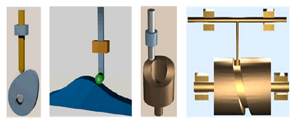
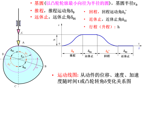
2. Mechanical cam model
3. Types of electronic cam
Track - track cam (path--path), it set up a track starting point and ending point for each cam in the cam wheel program, the cam is set while the actual position (angle or displacement)reaches the track start; and the cam is reset when the actual location reaches the track end. This type cam can obtain the nonlinear electronic synchronization between the two axles, and auxiliary shaft position can be synchronized to the spindle of used cam.
The path – time cam (path--time), it sets a track starting point and duration time for each cam in the cam program, The cam is set when the actual position reaches the track starting point, and then the cam is reset after the preset duration time. Such cam can obtain a motion profile different from trapezoidal or S-shaped.
4. Electronic cam implementation method
a. Set the spindle and auxiliary shaft
b. Set the electronic cam curve
c. Achieve electronic cam movement
Note: The electronic cam curve can adopt a variety of description ways, the common way is to use two-dimensional table describing the spindle and auxiliary shaft values; the mathematical formula can also be used to describe it. Many manufacturers have provided specific software tools to facilitate the generation of electronic cam curves
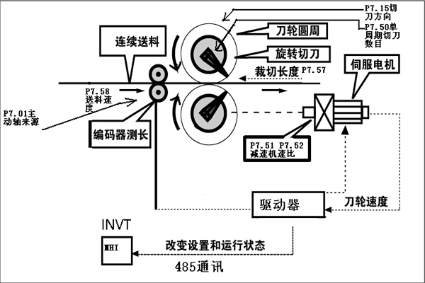
5. Cam application example
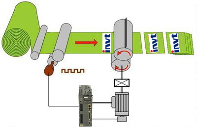
6. Flying shear speed curve
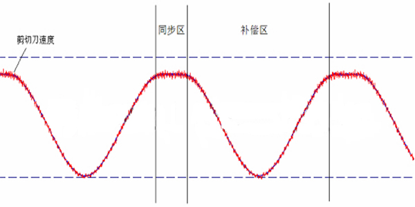
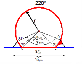
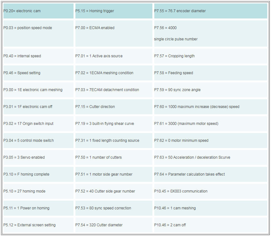
Synchronization angle (P7.59): The area where the cutter speed is the same as material advance speed. Figure, 0 - 80 degrees interval is the synchronization angle. Synchronization speed correction P7.53 is also involved in this area.
7. Apply thumbnails
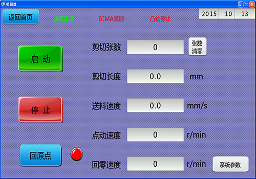
Process requirements:
a. The cutting number and the feed length are displayed on the touch screen. The cutting number cannot be changed but can be cleared. The feed length can be set and the real-time change is required (the next cycle is valid).
b. At the beginning of processing or in the machining process, there is a manual immediately cut button, press it, and then the cutter cuts immediately and does not affect subsequent processing; in the cutting process, random cutting off a piece of material is required for quality assessment.
c. Add an inching button, inching the cutter head for maintenance is required in the downtime of equipment.
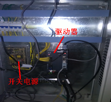
Hardware configuration:
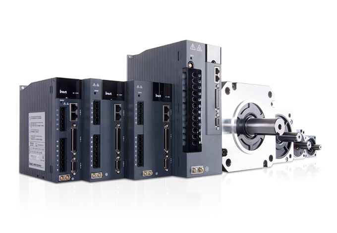
a. INVT DA200 servo (2.0kW)
b. INVT touch screen
c. Omron encoder
d. Zhongda reducer
8. Servo commissioning and parameter setting
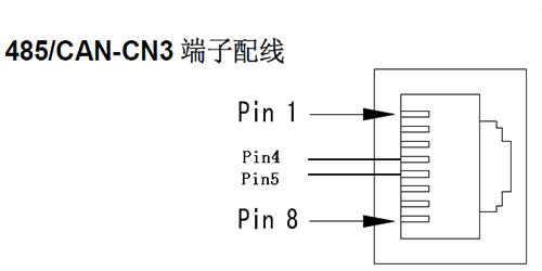
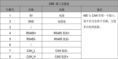
A.485 wiring
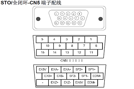
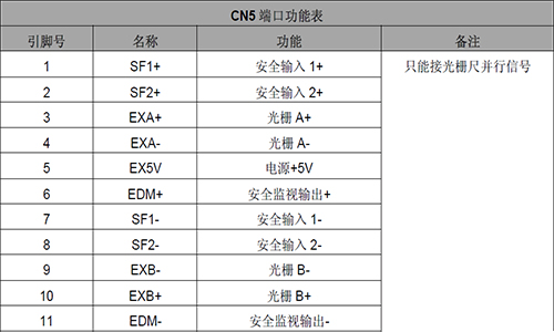
B. Hardware second encoder wiring
C. CN1 control wiring
DI1 (Electronic cam meshing port)
DI2 (Electronic cam detachment port)
DI3 (server enabled) emergency stop
DI5 (control mode switch port)
DI6 (Home switch input port)
DI8 ( set to 0 alternate port )
O1 (return to zero complete Output )
COM + COM

9. Precautions
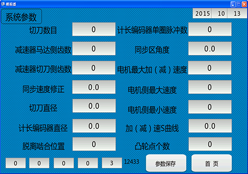
Cutter diameter: twice the distance from the cutter blade to the center of fixed cutter roll
Account the encoder diameter: it’s usually the periphery diameter of the second encoder roll wheel
Description A: Peripheral counting of the second encoder must be a differential output signal
Description B: Starting from the P7 group parameter, as long as the parameters related to the electronic cam curve, it’s needed to re-set P7.64 to 1 after setting (this parameter will automatically reset after setting), re-generate the cam curve, take effect in the next cycle.
Description C: electronic cam instructions of meshing and detachment given effect via communication, the system default is physical ports, you need to change DI1,DI2 to effective communication control, that is P10.45=3. Then write the number control corresponding to P10.46.
10. Conclusion
Through field test, the cutting accuracy of DA200 applied in gypsum board reaches 1mm, and other similar servo accuracy is about 3mm. Integrated cam function in the drive has eliminated the separate external motion controller, which has not only reduced the hardware cost, but also the wiring between motion controller and servo drive, reducing the possibility of electrical problems. Through setting the cutting size, the system automatically calculates the motion curve to achieve the cutting of different sizes, and achieve continuous switch between two orders coordinated with the production management system, minimizing the production of waste gypsum board.


Our site uses cookies to provide you with a better onsite experience. By continuing to browse the site you are agreeing to our use of cookies in accordance with our Cookie Policy.


 Share
Share
 Facebook
 Twitter
 Google+
 LinkedIn
 Return list