

In the process of placing orders, INVT will give customer a detailed list of spare parts, which will mark whether the spare parts are compatible with different models of VFDs; If the customer still has the previously ordered machine on site, it is necessary to confirm with INVT engineer whether it is compatible.
GD5000 VFD can be used for the whole machine container scheme, the standard IP level is IP54; Special IP class needs to be confirmed with INVT manufacturer.
The load of the mixer requires 150% current to last for 1 minute, so the selection of VFD is 1.66 times larger than the motor.
For the whole sugarcane mill line, located in the first press, the selection of the motor magnification 1.4 times, the remaining VFD magnification 1.2 times.
The GD5000 power cells don't has pre-charging circuit, but the whole VFD has a buffer circuit, which can pre-charge and buffer the cells.
The main interface cannot be accessed
First, determine the model of HMI. If it is TPC1062KI mode, it is a hardware problem. If it is TPC1061TH mode, first write HMI program to try. If the problem can not be solved, need to replace the HMI.
According to customer's requirements, we can supply gear switch cabinets and soft starters.
Check whether the power cell IGBT and drive board are abnormal; Whether there is abnormal insulation between VFD and motor.
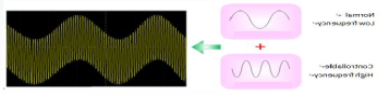
In the deceleration process of GD5000 VFD, 300Hz high frequency voltage is superimposed on the base frequency 0-50Hz, increase motor stator loss, so as to achieve the purpose of fast braking.


Our site uses cookies to provide you with a better onsite experience. By continuing to browse the site you are agreeing to our use of cookies in accordance with our Cookie Policy.