1.Equipment Introduction
Automatic solder paste printing presses are generally composed of printing plate mounting, solder paste, embossing, transmission circuit boards and other institutions. Its working principle is: First, fix the printed circuit board on printing position table, and then use left and right scraper on the printing press to print solder paste or red plastic in the corresponding pad through the steel net leakage, through transmission station, input the evenly printed PCB to patch machine for automatic patch. This equipment double Y-axis is the gantry structure connected by screw lever, maintaining the same speed on both sides in the process of high-speed positioning, which requires servo with gantry synchronization function.
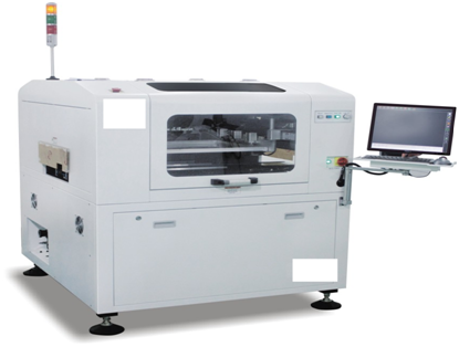
Table 1
2.Brief introduction of gantry synchronization
The usage of gantry synchronization focuses on controlling two mobile platforms to move at constant speed, if the movement between two axes exists too much difference, it will cause damage to the structure, so the synchronization moving controlling between two axes is the first priority of gantry synchronization usage.
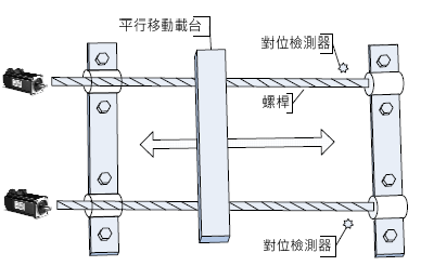
Table 2
Gantry synchronization control function provided by INVT DA200 series can meet the demand of users successfully. The drive will be self-synchronous control, when the position deviation exceeds set allowable value, it will issue a warning to stop the system operation.
P4.33 [Position tolerance pulse range] can set the alarm position tolerance threshold. A key point of gantry synchronization control is to ensure the parallelism of gantry; the first step is to keep the gantry straight through return to original function, during the process of back to origin, the host computer only gives a homing signal to the left and right servos , after touching the left and right original switches, the following homing action are completed by servo.
First of all, the host computer sends out homing signal to the host computer and slave computer at the same time, the host (slave)computer stops after touching the original sensor and wait for the slave computer to touch it. Two signals run back 1 turn (P6.38 = 10000) at the same time after being valid, then run forward and stop until touch the sensor switch, During the homing process, the host computer has been releasing the signal to slave computer gantry, it finally sends out gantry synchronization signal after completing contraposition.After the completion of gantry contraposition, the host computer sends out the mechanical homing signal; DA200 contains six kinds of built-in applications, the homing mode in different industrial control is provided for customers to choose.
Table 3
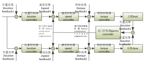
3. Gantry control principle:
As shown in the figure below, the gantry synchronization controller will read the position signals of master and slave computer in real time to obtain the difference of position and speed between master and slave computer, then output the speed and torque compensation commands to achieve the synchronous operation of master and slave computer.
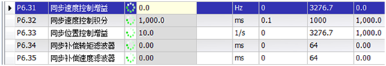
Set the host's P6.31 to P6.35 according to actual system.
4: Electrical wiring:
Host: pulse signal. Slave frequency dividing output. Servo alarm.
Origin start (DI1). Origin sensor (DI2). Homing completion (D01). Gantry synchronization release (DO2)
Slave: Pulse signal. Host frequency output. Servo alarm. Origin sensor (DI2) Gantry synchronization release (DI3)
| Host connection | |||||
| Angular position | definition | ||||
| 23 | PULSE+ | ||||
| 24 | PULSE- | ||||
| 32 | SIGN+ | ||||
| 33 | SIGN- | ||||
| 2 | V24+ | ||||
| 12 | V24- | ||||
| 15 | fault alarm | ||||
| 44 | 0A+ | 3 | EXA+ | Slave CN5 terminal | |
| 43 | OA- | 4 | EXA- | ||
| 41 | OB+ | 10 | EXB+ | ||
| 42 | OB- | 9 | EXB- | ||
| 16 | host is reset to zero | ||||
| 37 | Host origin switch | ||||
| 9 | gantry releasing | Output to the slave | |||
| 14 | Homing is completed | ||||
| 10 | Slave origin switch | ||||
| Slave wiring | |||||
Angular position definition
| 23 | PULSE+ | ||||
| 24 | PULSE- | ||||
| 32 | SIGN+ | ||||
| 33 | SIGN- | ||||
| 2 | V24+ | ||||
| 12 | V24- | ||||
| 15 | fault alarm | 3 | EXA+ | Host CN5 terminal | |
| 44 | 0A+ | 4 | EXA- | ||
| 43 | OA- | 10 | EXB+ | ||
| 41 | OB+ | 9 | EXB- | ||
| 42 | OB- | ||||
| 16 | slave is reset to zero | ||||
| 10 | gantry releasing | Receive host input |
5. Servo commissioning steps:
5.1.P6.30 open gantry synchronous switch;
5.2.Determine the host and slave according to the wiring of IO port (P6.37)
5.3.P4.62 grating ruler direction consistent with motor direction;
5.4.Online learning mechanical inertia (mechanical real-time load inertia ratio can be observed by R0.51)
5.5.Debugging gain according to the actual situation;
5.6.Set P4.64 parameters according to the situation (view gantry synchronization position deviation value through the R0.53)
5.7.According to the actual situation, decide whether you need to reverse the gantry synchronization alignment direction (P6.41) and gantry synchronization contraposition back distance (P6.37)
Specific parameters are set as follows :
| host | slave | |||
| P0.22=10000 | pulse per revolution | P0.22=10000 | pulse per revolution | |
| P0.24=1 | reversed negation | P0.24=1 | reversed negation | |
| P1.01=600 | inertia ratio | P1.01=600 | inertia ratio | |
| P3.00=0X108 | Return to zero | P3.00=0X108 | Return to zero | |
| P3.01=0X02E | Host origin switch | |||
| P3.02=0X02F | Slave origin switch | P3.02=0X02D | Gantry releasing | |
| P3.05=103 | enabling | P3.05=103 | enabling | |
| P3.10=0X00F | Homing is completed | |||
| P3.11=103 | The alarm polarity is reversed | P3.11=103 | The alarm polarity is reversed | |
| P3.14=0X01E | Gantry releasing | |||
| P4.64=1000 | Mixing deviation is too large | P4.64=1000 | Mixing deviation is too large | |
| P6.30=1 | Gantry synchronization function switch | P6.30=1 | Gantry synchronization function switch | |
| P6.33=48 | Synchronous position control gain | P6.33=48 | Synchronous position control gain | |
| P6.37=1 | Gantry synchronization master and slave selection | P6.37=0 | Gantry synchronization master and slave selection | |
| 6.38=1500 | Gantry synchronization contraposition backwards distance | P6.38=1500 | Gantry synchronization contraposition backwards distance | |
| P6.41=1 | Gantry synchronization contraposition direction | P6.41=1 | Gantry synchronization contraposition direction | |
| take effect after changing the parameters and turning off the power |
6. Gantry synchronization program summary:
6.1.DA200 built-in gantry synchronization function, simplify the upper controller, reduce control costs;
6.2.High precision, repeat positioning accuracy 1mm;
6.3.Safe and reliable operation, when any host or slave servo alarms, the gantry immediately stops;
6.4.Synchronous debugging is convenient.


Our site uses cookies to provide you with a better onsite experience. By continuing to browse the site you are agreeing to our use of cookies in accordance with our Cookie Policy.


 Share
Share
 Facebook
 Twitter
 Google+
 LinkedIn
 Return list