Abstract: This paper analyzes the running characteristics of portal crane, and elaborates the selection principle of motor, inverter and its braking mode and the capacity calculation method of the inverter peripheral equipment when CHV190 crane special inverter is used in portal crane speed adjusting, and finally introduces the application case of CHV190 inverter in portal crane.
Keywords: INVT CHV190 crane dedicated drive, portal crane, electrical brake
1.Preface
With the industrial production’s requirements for crane speed control performance continue to improve, common traditional crane speed control methods include: winding rotor asynchronous motor rotor series resistance speed control, thyristor stator voltage regulator and cascade speed control. Their common disadvantage is that the winding rotor asynchronous motor includes collector ring and brush, which require regular maintenance. And the failure caused by collector ring and brush is more common, coupled with the usage of numerous relays and contactors, they result in a large amount of on-site maintenance, high failure rate of speed control system, and the poor comprehensive technical indicators of speed control system can not meet the special requirements of industrial production.
AC variable frequency and speed control technology is widely used in the industry and has provided a new program for large-scale, high-quality speed control of crane driven by AC asynchronous motor. It has a high performance speed indicator with a simple structure, reliable, easy maintenance cage cage asynchronous motor, which is efficient and energy saving. The external control circuit is simple with small maintenance workload, perfect protection and monitoring function, the operational reliability has greatly improved compared to traditional AC speed control system. Therefore, AC frequency control is the mainstream of crane AC speed control technology development.
The application of AC variable frequency speed control technology in crane can bring the following significant benefits compared to traditional winding asynchronous motor rotor series resistance speed control system widely used in the market.
(1) Due to the mechanical characteristics of motor driven by inverter, Crane adopting AC variable frequency speed control technology has the advantage of precise positioning, the rotational speed of motor won’t change when the conventional crane load changes, which can improve the productivity of loading and unloading operation.
(2) Variable frequency crane has advantages of smooth running, gentle starting and braking, while acceleration and deceleration, the machine vibration and shock has significantly reduced and safety has been improved, which has extended the life of crane mechanical part.
(3)Mechanical brake works in the low-speed of motor, the main hook, truck and car brake are completed by the electrical brake, so the brake block life of mechanical brake has been greatly extended and the maintenance costs has declined.
(4) Adopting the cage cage asynchronous motor with simple structure and high reliability to replace the winding rotor asynchronous motor, which has avoided the fault of motor damage or unable to start caused by poor contact that is brought about by collector ring, brush wear or corrosion.
(5) With great reduction of AC contactor, the main circuit of motor has achieved non-contact control, which has avoided the contactor kit burning caused by frequent operation and motor damage due to contactor kit burning.
( 6 ) Based on site conditions, AC variable frequency speed control system can flexiblely adjust each shifting speed, acceleration and deceleration time, ensuringing the flexible operation and good adaptability of variable frequency crane.
( 7 ) AC variable frequency speed control system is an efficient speed control system with high running efficiency and low heat loss, so it can save a lot of energy compared to the old speed control system.
(8) The converter has the perfect function of protection, monitoring and self diagnosis, and it can greatly improve the electric control system reliability of variable frequency crane combining with PLC control.
2 .Characteristics of portal crane
The portal crane is a device of lifting, unloading and transporting heavy objects and moving heavy objects within a certain range, playing an important role in production process. The portal crane system is divided into lifting (grappling portal machine is composed of the support, closed body composition), amplitude, rotation, walking four parts.
Portal crane is developed with the port industry development. In the developing process, portal crane is also popularized to the berth and hydropower station where the operating conditions are similar to port. According to the usage, it can be divided into three categories: ① loading and unloading portal crane: It’s mainly used for ports and open pit, loading and unloading via a grab or hook.
The general weight won’t surpass 25 tons or change with the range. Due to the high working speed, productivity is often an important indicator. ② portal crane for manufacturing ships: it’s mainly used for berth, floating dock and fitting-out scene, the hull stitching, equipment fitting-out, and other lifting operations, with the hook as spreader. The maximum weight of 300 tons, and the weight begins to decline in the large magnitude.
There are multi-range lifting speeds, and the speed can be improved in the light weight. Some working mechanisms are also equipped with micro-devices to meet the installation requirements. High portal height can adapt to the large lifting height and operating requirements, but the work speed and job productivity both are low. ③ portal crane for construction and installation: It’s mainly used in hydropower stations for dam pouring, equipment and prefabricated parts, etc., generally with a hook. The weight and working speed are generally between the first two cranes. It has a good assembly and disassembly transport, large spreader down depth, which can better adapt to the temporary work and the work on trestle.
2.1 Usage environment
Most of the portal cranes are used in open air environments such as wharf, freight yard and heavy industry enterprises. The outdoor temperature changes drastically, and there are dust and corrosive gases in some places, the usage environment is bad. The vibration and shock of portal crane are large in operation, there are small transformer capacity, small power supply cable cross-section, long cable and other problems in the power supply aspect; it often causes instantaneous undervoltage in the lauching of large-scale equipment.
2.2 Institutional composition and operational characteristics
Portal crane includes lifting, turning, changing and operating mechanisms, the first three institutions are installed in the rotating part and participate in operations in each cycle. The rotational section is also equipped with a tilted single-arm or combined boom and driver room. The operating mechanism is installed in the lower part of portal crane to adjust the working position of crane. The bucket portal crane is also equipped with additional equipments such as telescopic funnel and belt conveyor to improve the productivity of gantry crane when loading the bulk material with the grab. In addition to electrical protection devices, it’s also equipped with weight or lifting torque limiter, crane rail climp and other safety devices.
The various types of mechanisms for portal cranes are constant torque load; in addition, different mechanisms also have their own characteristics.
(1) The lifting mechanism has a bit energy load because it has a bit energy in space. It is characterized by: when the heavy objects rises, the motor must overcome a variety of resistance (including heavy objects’ gravity, friction resistance, etc.) and work, which belongs to resistance load; When the weight falls, since the weight itself has the ability to decrease according to the acceleration of gravity (bit energy), When the gravity of heavy objects is greater than the frictional resistance of transmission mechanism, the gravity of heavy object itself (bit energy) is the downward power, the motor becomes the recipient of energy, which belongs to the power load; But when the gravity of heavy object is less than the friction of transmission mechanism, the heavy object still needs to be dragged by the motor, which belongs to the resistance load.
(2) Amplitude, rotation, walking agencies are resistance load. But these bodies of outdoor cranes sometimes become dynamic loads in larger wind conditions.
(3) The crane shall have a large starting torque, usually exceeding 150% of the rated torque, and taking into account factors such as overloading, at least 200% of the rated torque shall be provided during the start-up of acceleration.
(4) Due to the existance of mechanical brake, the control timing of starting signal of inverter and operation signal of mechanical brake must be fully discussed in order to smoothly switch the output torque of inverter and braking torque of mechanical brake.
(5) When the hoisting mechanism is running down or the motor is decelerating, the motor will be in the regenerative state. The energy should be fed back to the power supply side. It is necessary to discuss how to deal with this part of regenerative energy according to different scene conditions.
(6) The load of lifting mechanism dramatically changes in the moment of lifting the heavy objects leaving or contacting the ground, the frequency drive should be able to smoothly control this kind of impact load.
3.Motor selection
When the power supply of the cage asynchronous motor is provided by the inverter, because the inverter sold on the market mostly use PWM modulation. Compared to industrial frequency power supply, there are some new problems due to the impact of high harmonics and the expansion of motor operating speed range.
(1) The effect of harmonics
When the general inverter with PWM modulation is used to provide power supply for the cage asynchronous motor, the stator current of the motor is rich in high harmonics, and the iron loss and copper loss of the motor caused by the high-order harmonic starts to increase, which causes the temperature rising of the motor.
Statistics shows that in the rated state of the motor, compared to the industrial frequency power supply, the current of inverter power supply motor has increased by 10%, while the temperature rising by about 20%. When selecting the motor capacity, user should leave some margin to prevent too high temperature rising of motor, affecting its lifetime.
In addition, when the size of motor is greater than 280, in order to avoid the shaft current caused by the occurrence of high-order harmonic, the motor should be installed with the insulation bearing on the non-drive end. And in order to further reduce the bearing current, shielded motor cable should be used, and the motor shell should be well grounded.
(2) The impact of cooling capacity
The cooling capacity of standard cage motor is measured by the cooling air volume of the cooling fan installed on the motor shaft at the rated speed. In the speed control operation of motor, in the rated rotational speed below, the cooling capacity becomes worse with the decline of rotational speed. The lifting and travelling machenism of portal crane is constant torque load. In order to ensure that the temperature rising of motor is within the permissible value in the low speed operation, the frequency conversion dedicated motor should be used.
Now the frequency convertion dedicated motor released in the domestic is composed of the ordinary cage asynchronous motor and an independent fan, which has improved the insulation capacity of motor winding and expanded the speed control range of the motor,it can be continuously operated in the range of 3-100Hz. 3-50Hz range is constant torque operation, 50-100Hz range is constant power operation.
(3) The impact of motor insulation
Most of the general-purpose inverters sold on the market today use PWM modulation and IGBT inverter technology, the output voltage consists of high-voltage pulse, the peak value is about 1.35 times the grid voltage. Depending on the characteristics of the motor cable and different distance of the power supply, the peak value of pulse voltage may be doubled at the motor wiring terminal, which places a higher requirement on the insulation of motor. For details, refer to the manual provided by the inverter manufacturer or consult to the motor manufacturer.
4.Inverter selection
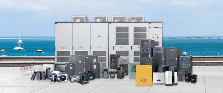
4.1 Brief introduction of the dedicated inverter for INVT CHV190 crane
4.1.1 Introduction to main functions
CHV190 crane dedicated inverter is a high-performance vector inverter designed by INVT for lifting industry. It is used for the stepless speed regulation of lifting, pitching, luffing, cart, trolley, turning and grazing and other machnisms of various cranes. The main features and features are as follows:
(1) Brake logic control and monitoring, pre-excitation and start the pre-torque compensation
Accurate brake opening and closing control timing, through the brake real-time state, feedback and start the pre-torque compensation to ensure the safety and reliability of control.
Pre-excitation function is to directly conduct DC excitation to the motor before the starting of motor to ensure that the motor can quickly provide the starting torque, and adjusting the excitation time to coordinate the release time between the start of motor and the mechanical brake to avoid the "hook gliding" phenomenon.
(2) Light load speed upgrading (electronic vice hook) and loose rope detection
Crane of empty hook or light load can achieve 2 times operation speed and improve handling efficiency. Light load speed upgrading function is mainly used in the crane with large height hoisting:
In the no-load operation of hoisting mechanism, automatically increasing the speed to shorten the time to improve handling efficiency; in the condition of overload, automatically reducing the speed to ensure the safety of equipment and personal.
The inverter determines the load size according to the average current value in a certain period of time after starting: The inverter automatically reduces the output frequency when the load is heavy. When the load is light, the inverter will automatically increase the output frequency. The loose rope detection function prevents unsafe operation caused by malfunction of the light load speed malfunction when the crane rope is loose.
(3) The control circuit power and main circuit power can be controlled separately to improve the safety of user debugging, and is convenient for fault diagnosis and maintenance.
(4) Master and slave control power balance and speed synchronization technology
when the two high-power motor drive a hoisting mechanism through the gear box rigid connection, the master and slave control power balance function can ensure the even output of two motors; When the double lifting mechanism lifts a heavy pbject, the master and slave control speed synchronization function will ensure the synchronized lifting of two lifting agencies and the safety.
(5) Second motor control and switching function
An inverter can automatically store two sets of motor parameters through the parameters self-learning, and the command switch can achieve the high-performance motor vector control of two groups motors; it facilitates the control of electrical drive system and can reduce user costs.
(6) It can support PROFIBUS-DP and MODBUS, INTERNET various communication protocols and achieve the communication between multiple inverter and PLC.
(7) Dangerous speed monitoring, fast stop and overspeed protection
The inverter monitors the running speed of the motor in real time, When the motor speed is greater than the set maximum allowable speed or speed deviation value, the inverter sends out fault alarm and stops output immediately, and the mechanical brake moves to ensure the crane in the safe state.
The quick stop function gives users the following three options:
Mode 1: parking of electric brake; mode 2: electric brake plus mechanical brake parking; mode 3: mechanical brake parking.
(8) Crane operating mode
According to the different operating modes of crane, the following operating modes are provided: joystick mode, remote control mode, electric potentiometer mode, graded joystick reference mode, hierarchical remote given mode, communication reference mode and so on.
4.1.2 Application range
CHV190 crane dedicated vector inverter has excellent torque control performance and is widely used in the stepless speed regulation exchange of lifting, variable amplitude, carts, trolley, rotary, grapple and other institutions of shore container cranes (STS), rail container gantry cranes (RMG), tire container gantry cranes (RTG), portal cranes, shipbuilding gantry cranes, shipping machines, ship unloading machines, tipping machines, stacking machine and other types of port machinery; as well as various ordinary bridge, portal, tower crane and girder crane, bridge erecting machine and other lifting machineries.
4.2 Inverter capacity calculation
Here is the detailed description to the inverter selection principle of lifting, travelling (rotary) mechanism of portal crane.
(1) Hoisting mechanism
the motor shaft output power required for the hoisting mechanism of portal crane:
Wν
PM = ————
6120η
Where W - hoisting mechanism rated lifting load weight, kg
ν- the rated speed of hoisting mechanism, m / min
η- mechanical efficiency of hoisting mechanism
The capacity of inverter must be greater than the output required for load, ie,
k PM
P0[KVA] ≥ ————
ηcosφ
Where k - overload factor 1.33
PM - load required motor shaft output power, kW
η- motor efficiency
cosφ- the power factor of motor
The starting torque required for the hoisting mechanism is 1.3-1.6 times of the rated torque, taking the 125% overload requirements into account, the maximum torque requires 1.6-2 times of the rated torque to ensure its safe usage. For driving the inverter of an equivalent power motor, an overload capacity of up to 60 seconds and 150% rated torque can be provided, so the overload factor k = 2 / 1.5 = 1.33.
After the selection of inverter capacity, it should also be verified by current, ie:
ICN≥kIM
Where k - current waveform correction factor (PWM modulation mode takes 1.05-1.1)
ICN - rated output current of the inverter, A
IM - rated current of motor in the industrial frequency power
The general large tonnage crane has two independently driven hoisting mechanisms, each of which is driven by the respective wire rope reel driven by two motors simultaneously and then lifting the hook through the multi-stage deceleration of the moving pulley group. The frequency conversion speed control and transmission scheme of the hoisting mechanism adopts a "one drag one" scheme of an inverter driving a motor. In order to improve the dynamic characteristics and high torque output capability in the low speed transmission, each motor adopts the speed closed loop control with pulse encoder.
The two converters of each hoisting mechanism adopts the master and slave control program with power balance and speed synchronization control function provided by CHV190 inverter, these control programs can achieve the precise torque balance distribution of two motors and the speed synchronization of two hoisting machenisms.
(2) Travelling, rotating body
The travelling and rotary mechanism of portal crane mostly adopts multiple motors transmission program. Due to the large rotational inertia of the gantry crane travel mechanism, large starting torque is required for the acceleration of motor, So the output power PM of the motor required by the portal crane traveling mechanism should be composed of the load power Pj and acceleration power Pa, that is:
PM≥Pj+Pa
The load power required for the travelling mechanism is:
µ Wν
Pj = ————
6120η
Where μ - the friction coefficient of travel mechanism
W - the weight of the rated load of travel mechanism, kg
ν- rated speed of travel mechanism, m / min
η- Mechanical efficiency of the walking mechanism
The acceleration power required for the walking mechanism is:
knM GD²nM
Pa = ————— × ————
974ηcosφ 375 tA
Where k - current waveform correction factor (PWM modulation mode takes 1.05-1.1)
nM - the motor rated speed of the travel mechanism, r / min
cosφ——The power factor of the motor
η—— motor efficiency
GD²——total inertia of the travel mechanism converted to the motor shaft, kg • m²
tA——Motor acceleration time (according to load requirements), s
As the walking mechanism mostly uses the universal U / f open loop frequency control mode of an inverter dragging multiple motors, so the selection of inverter capacity should also meet the following formula:
ICN≥knIM
Where k - current waveform correction factor (PWM modulation mode takes 1.05-1.1)
ICN——Rated output current of the inverter, A
IM——Rated current of a single motor in the industrial frequency power supply, A
n——一The number of motors that a drive drags
5.Regenerative energy treatment
When adopt the hoisting mechanism transmitted by the inverter to drag the down-pass of bit load or the rapid deceleration, downwind operation of the travelling mechanism, the asynchronous motor will be in the regenerative power generation state. The six feedback diodes in the inverter convert the mechanical energy of transmission mechanism into electrical energy and feed back it to the intermediate DC circuit, causing the voltage rising in the two ends of energy storage capacitor. If the necessary measures are not taken, the inverter trips due to the overvoltages when the DC circuit capacitor voltage rises to the protection limit.
In the high-performance engineering inverter, there are the following two options to the processing of continuous regenerated energy. ① Set the resistor in the middle of DC circuit, so that the continuous renewable energy can be comsumed in the form of heat via the resistor, this way is known as the dynamic braking; ② Adopt renewable rectifier, send the continuous regenerated energy back to the power grid, this way is known as the feedback brake. The specific parameters of the DBU type energy consumption braking unit and the RBU type energy feedback unit introduced by INVT can be found in the instruction manual.
The following is a detailed description to the two types of braking.
(1) Dynamic braking
The power brake is composed of a braking unit and a braking resistor. After the inverter sets the braking unit and the braking resistor, its power braking capacity depends on the allowable power of the braking resistor.
Therefore, when calculating the regenerative power PM, the PM <PR (PR is the allowable power of the braking resistor) must be satisfied. If the regenerative power exceeds the allowable power of the braking resistor, the deceleration time and the load inertia must be reconsidered. The following describes how to calculate the regenerative power PM and the resistance value RB of the braking resistor after setting the braking resistor.
① Calculate the regenerative energy EM
② Calculate the regenerative power PM
PM = EM/t0
Where PM - the effective regenerative power generated by the motor during braking, W
EM——regenerated energy in the rapid deceleration and decline of mechanism, J
t0——Braking cycle time, S
③ Select the appropriate brake unit / brake resistor combination
Select the appropriate combination of brake unit / brake resistor, the following conditions must be met:
PM<PR&PM<PDB
Where PM—— the effective regenerative power generated by the motor during braking, W
PR——The allowable power of the braking resistor, W
PDB——The allowable power of the braking unit, W
When the calculated PM>PR, it indicates that the processing capacity of the braking resistor is exceeded, and the load inertia and deceleration time need to be recalculated.
④ calculation of the braking resistor RB0
In the regenerative feedback brake, even if the braking resistor is not provided, the braking torque of about 20% can be obtained by the internal loss of the motor. Therefore, the required resistance value RB0 can be calculated by the following equation:
VC²
RB0 = ——————————
1.027(TB-0.2TM)n1
Where VC—— the intermediate DC circuit voltage of the inverter (about 700V), V
TB——Braking torque, kg • m
TM——Motor rated torque, kg • m
n1——The speed when the motor starts decelerating, rpm
The dynamic braking discharge circuit consists of a braking unit and a braking resistor, its maximum current is limited by the maximum allowable current IC of the brake transistor, and the minimum allowable value of braking force RMIN=VC/IC. Therefore, while selecting the braking resistor, the actual value RB should meet the following conditions:
RMIN < RB < RB0
The above selection is based on accurate calculation, in the actual project, if the exact calculation data can not be obtained, it can also be given as follows empirical formula selection.
① Regenerative power of hoisting mechanism PM
PM = Pb×ηtotal
ηtotal=ηmec×ηmot×0.98
In the above equation, Pb is the regenerative power generated power of the actual load, ηmec is the mechanical efficiency, and ηmot is the motor efficiency.
② approximate calculation of the braking resistor RB0
VC²
RB0 = ——
PM
As the travelling mechanism belongs to the friction load, the braking unit and braking resistor can be arranged according to the standard of inverter.
(2) Feedback brake
In order to feed back the regenerative power generated power of motor in the braking state to the power grid, the network side converter should adopts the reversible converter. The energy feedback brake unit introduced by INVT, its network side converter is the same to the inverter structure, and it adopts a power grid voltage identification board with PWM control mode. Due to the adopting of PWM control technology, the size and phase of the network side AC voltage can be controlled; you can make the AC input current and power grid voltage in the same phase and close to the sine wave, the power factor of transmission system is greater than 0.9, there is 100% power grid feedback capability in the brake feedback without autotransformer.
Power brake control is simple, low cost, but the energy efficiency is not as good as feedback brake. Although the feedback braking method has a good energy-saving effect and can continue a long brake, its control is complex with high cost. It should be noted that the feedback braking mode can be used only in the case of a stable power grid voltage that is less prone to failure. For cranes with trolley conductor, special care should be taken to prevent intermittent contact of the trolley conductor wire brush. If this is not guaranteed, it is recommended to use a dynamic braking method to ensure the reliability of the speed control brake when the hoisting mechanism continues to fall.
6.Wiring design
6.1 Main circuit of the inverter
The inverter of the hoisting machenism of the portal crane adopts the vector control mode, the motor constants of the transmission motor are used, the data is obtained by the parameter self-detection program of the inverter. If select the motor wiring according to the conventional wire heating test, in the long-distance power supply, the line impedance is added to the motor data from the parameters self-detection, causing the decline of inverter control accuracy, and fail to meet the design requirements.
In addition, the laying distance between the inverter and the motor is long, the line voltage drop is large, and the motor torque is sometimes insufficient. In particular, when the inverter output frequency is low, the output voltage is also low, the proportion of line voltage drop increases. The line drop between the inverter and motor shall not exceed the rated value of 2% rated voltage. The cross section of motor cable can be selected accordingly.
Since the parasitic capacitance is present in the output wiring of inverter, its capacity is proportional to the length of motor cable. The larger the parasitic capacitance of motor cable, the greater the leakage current in the inverter output cable with PWM control, which causes the output of inverter is not enough. Therefore, in the portal crane wiring design, user should strive to reduce the inverter to the total length of motor cable.
6.2 Control circuit
The inverter control signal is the weak voltage, current signal, so different from the main circuit, the inverter output circuit is a strong electromagnetic interference source. Therefore, the wiring of the inverter control circuit can not be laid in the same pipe or the same wiring harness as the main circuit wiring of the inverter. In order to further improve the anti-jamming effect, 1.0mm2 insulated shielded wire should also be used.
Insulated shielded conductor grounding should be the single point grounding in the inverter side, it should use dedicated ground terminal and not share with other ground terminals. Electromagnetic induction interference size is proportional to the wire length, so as far as possible to lay the line in the shortest time. In the case of serious electromagnetic interference, in addition to take grounding, shielding and other measures, install the data filter in the inverter control signal line to further reduce the impact of interference voltage.
7. Application of CHV190 crane special inverter in 25t-35m portal crane
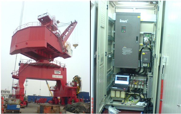
7.1 The main parameters of 25T-35M portal crane are as follows:
(1) Rated lifting capacity: 25m under the hook 40T; grab 25T;
(2) Lifting height: 20m on the grab track; 15m under the rail; 28m on the hook rail; 15m under the rail;
(3) Range: maximum 35m, minimum 10m;
(4) Operating speed of working agencies
① Lifting speed: hook rated 25m / min; grab rated 50m / min; no load 60m / min;
② Rotation speed: 0.8 (amplitude 30-35m) / 1.2 (amplitude 10-30m) rpm;
③ The average speed of amplitude: 45m / min;
④ Travelling speed: 25m / min;
(5) Power: 3-phase 380V, 50Hz
(6) the whole machine work level: A8
7.2 Electrical transmission single line diagram
(1) Hoisting mechanism
The hoisting mechanism of MC type 40T grab portal crane is composed of the support, closed mechanism, two machenisms are driven by a 160KW variable frequency motor, the speed is controlled by the closed-loop vector with encoder, adopt INVT crane dedicated inverter CHV190-220G -4; Brake unit is DBU-315-4, braking resistance: 2Ω80KW; it belongs to the stall stepless speed control mode, adopt profibus-DP on-site bus control, and it’s equipped with S-curve acceleration and deceleration mode to ensure the stability in the lifting process.
(2) Pitching institutions
The pitching mechanism is driven by a 132KW variable frequency motor. The speed is controlled by the closed loop vector with encoder, and it adopts INVT crane dedicated inverter CHV190-185G-4; the braking unit is DBU-315-4, braking resistor: 2Ω60KW; It belongs to a stall stepless speed control mode, using Profibus-DP field bus control, and it’s equipped with S-curve acceleration and deceleration mode to ensure the stability of amplitude process of hoisting mechanism.
(3) Carts machnism
The cart operating mechanism is driven by four sets 11KW variable frequency motors, and shares the same inverter with the support mechanism, it’s controlled by switching. When one of the motors needs to control the operation, the inverter automatically switches to the corresponding motor group parameters after receiving the conversion signal.
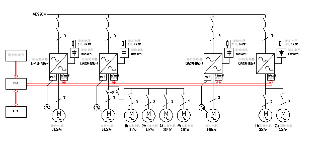
(4) Rotating mechanism
The rotating mechanism is driven by two sets 30KW variable frequency motors, and the speed is controlled by open loop vector. It adopts INVT crane dedicated CHV190-110G-4. The brake unit is DBU-220-4, braking resistor: 4Ω20KW; It belongs to stall stepless speed control mode, using Profibus-DP field bus control, and it’s equipped with S curve acceleration and deceleration mode to ensure the start brake smooth of the large inertia load and stable operation of rotating mechanism.
7.3 System advantages
(1) Reliable brake logic control, and the brake time is adjustable, avoid the motor's large current shock at the same time of ensuring no hook gliding.
(2) High-performance closed-loop vector control, it can output 180% the rated torque up to 10S at zero speed, increasing the system reliability.
(3) lifting machinery adopts light load speed upgrading(electronic vice hook) function, running between 0-50HZ while lifting objects, running between 0-100HZ in the condition of empty hook to improve the work efficiency;
(4) Multi-speed or analog speed adjustment, acceleration and deceleration process are in accordance with the S-curve mode, increasing the work stability, reducing the mechanical impact, extending the equipment lifetime.
(5) After multi-motor parallel, the inverter automatically identifies the parameters and establishs an effective mathematical model with very high control accuracy.
(6) Single inverter switching control 2 sets of motors, automatically identify and store two sets of motor parameters, both can achieve high performance control. Reducing the whole machine cost of the equipment and greatly improving the competitiveness of the whole machine.
(7) Adjustable torque compensation to achieve precise control.
7.4 On-site commissioning of the inverter
Limited by the lenth of essay, the following takes the debugging process that supports the inverter as an example, a brief introduction to the debugging process of CHV190 inverter.
(1) Motor parameter identification
Identify the motor parameters starts in the case of motor shaft and load off, first set the motor parameters P2.00-P2.05 and encoder parameters P4.00-P4.01, and then set P0.07 to 1 for motor parameters self-learning, the main parameters are as follows:
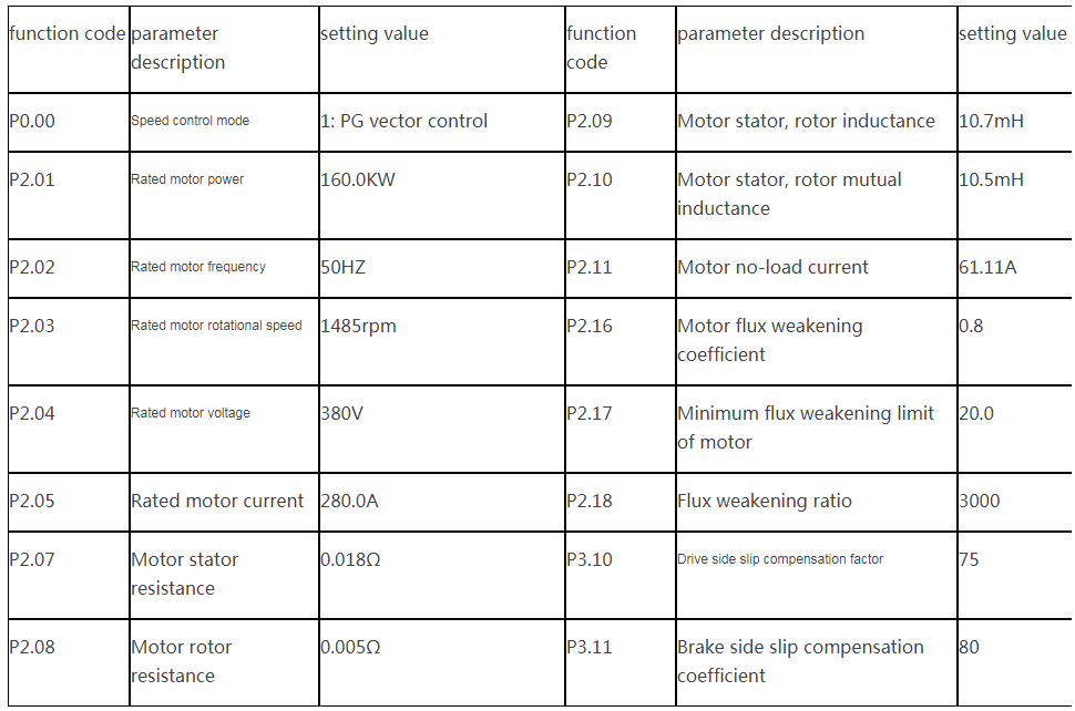
After the completion of self-learning, set the speed no-load closed-loop vector operation from low to high, observe the no-load current and motor operation to ensure normal.
(2) Setting of other parameters
P0 group (basic function group), P1 group (speed curve group), P4 group (encoder parameter group), P5 group (input terminal group), P6 group (output terminal group) and other parameters can be set according to actual needs.
(3) Brake timing control test
Modifying the P8 group to enhance the brake closing, brake-releasing delay, shutdown delay and other parameters of the functional group, and debug the brake timing control.
(4) Closed-loop vector operation with load and verify the light load speed upgrading (electronic vice hook) function
Observe the brake timing control is normal and then install the spindle linkage, set the speed to run from low to high speed steps. In debugging with load, adhere to debugging in the steps from the light load to the heavy load, and observe the inverter running current and motor running status. Modifying the light load and speed upgrading enable parameter in the P8 group (enhanced function group), verify the running between 0-50HZ during lifting the heavy object and the running between 0-100HZ when the hook is empty.
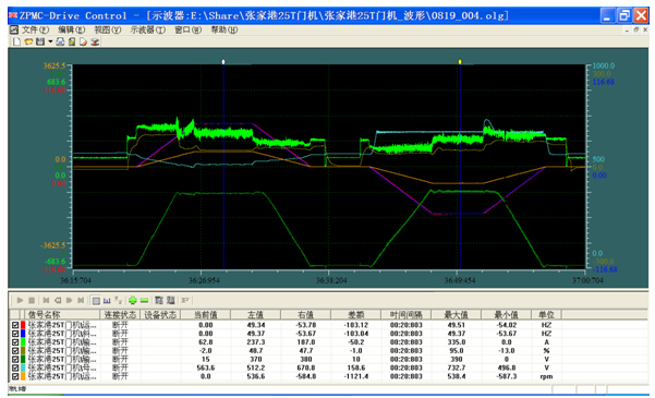
(5) Debugging waveform
8. Conclusion
With the continuous development of power electronics technology, AC variable frequency speed control technology is increasingly showing excellent control and speed control performance, high efficiency, easy maintenance and other characteristics, coupled with its price declining, making it a preferred crane speed control program. However, in order to successfully apply the inverter to the crane speed control, on account of the characteristics of the crane, calculate and select the inverter and its peripheral accessories, and take special technical measures in the installation and wiring to ensure the safety and reliable operation of frequency conversion speed control crane.
References:
1. INVT • CHV190 frequency conversion converter operating instructions [Z] • 2009 •
2. Han Anrong • Universal inverter and its application [M] • Mechanical Industry Press • 2000 •
3. Duan Suzhen • Application of AC Variable Frequency Speed Regulation Technology in Gantry Crane [J] • Electrical Transmission, 2005,1 •
4. Duan Suzhen • AC variable frequency speed control of the electrical brake mode [J] • Machine Tool, 2004,3 •


Our site uses cookies to provide you with a better onsite experience. By continuing to browse the site you are agreeing to our use of cookies in accordance with our Cookie Policy.


 Share
Share
 Facebook
 Twitter
 Google+
 LinkedIn
 Return list