
 Facebook
 Twitter
 Google+
 LinkedIn
To communicate with some industry customers, recently I heard a "novelty" : a manufacturer of modular UPS has a wonderful functions, is a single power module can be used independently as a full UPS, and as a big selling point. It seems that marketing needs to keep up with The Times. Is this not the modular UPS of the previous "decentralized bypass"? The technology that hasn't changed in more than a decade is now being packaged as a new selling point, which is "knowledge is power".
People familiar with the development of modular UPS should know that the modular UPS system has two different technical routes from the beginning: decentralization and concentration bypass. The author wants to compare the choice of these two options from the source of technology and the reliability of performance, hoping to give readers some inspiration and help.
1. Definitions and sources of the two types of bypass schemes
Modular UPS, just as its name implies, is the high-power UPS system, separated into many sub modules in parallel, through the optimization of system control, realizes the system expansion and online upgrade, maintenance, and significantly improve the system reliability, availability, and energy saving effect, reduce the maintenance cost of customers in recent years has gradually become the mainstream of choice for customers. The following is an analysis of the typical 300kVA system based on 10 30kVA power modules in the market.
(1) Decentralized structure
Scattered bypass architecture, that is, each power module contains rectifier and inverter and battery, and other parts, also contains equal static bypass capacity and power module, can be thought of as a UPS without LCD monitor. Multiple modules are connected in parallel in the cabinet, and the inter-module relationship is similar to that of the traditional multi-parallel UPS system. When the system switches to the bypass power supply, the load is connected in parallel by the scattered bypass in all power modules. The system architecture diagram is shown in figure 1.
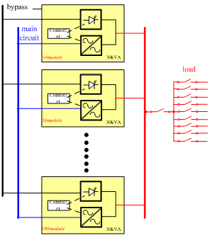
Figure 1. Scatter diagram
(2) Centralized bypass architecture
Bypass architecture, system only an equal concentration of bypass module and system capacity, power module contains only within the rectifier and inverter and battery conversion circuit, by an independent controller in every part, the parallel between modules is no longer the traditional UPS weaver system, but contains complex inverter are flow, bypass control and monitoring logic. The system architecture diagram is shown in figure 2.
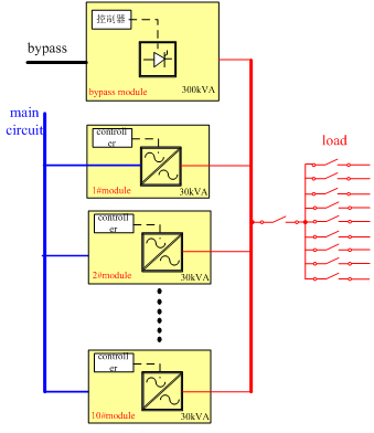
Figure 2. Centralized bypass architecture diagram
(3) The source of the two technical solutions
Customers the concept of modular UPS, originated in the demand for system maintenance facilitation, hope to not influence the critical business under fault condition, and simple replace resumed operation system. It is natural for the manufacturer to design a modular structure of the UPS parallel machine system, which is the source of the dispersed bypass scheme.
The advantages of the dispersion bypass scheme are: control simple, the development difficulty is small, only need to transfer the original UPS parallel machine system and optimize the monitoring part; Low cost of cabinets; The bypass devices are relatively small and relatively low cost. Static bypass is redundant.
Bypass solution concentration is developed after scattered bypass technical route, compared with the traditional weaver UPS system, from logic control flow, system coordination, fault tolerant ability to do the very big change, is a new technology, the development is difficult.
The following sections describe the performance and reliability differences between the two technical routes.
2. Performance differences between the two schemes
Static bypass as the last barrier of UPS power supply, the importance is self-evident, common bypass the situation of the power supply has the following kinds: inverter, inverter overload or temperature, output short circuit. As can be seen, the operating condition of the by-pass power supply is extremely extreme condition, the appraisal of the device should be doubly harsh.
(1) The steady state condition
Bypass the power supply, centralized bypass scheme is easy to understand, only offer a bypass all current, maximum capacity to bypass capacity according to the system design, has nothing to do with the number module configuration, there is no problem.
Scattered bypass solution is made up of multiple small power static bypass to bear the load, due to the bypass circuit is low resistance circuit, multi loop flow there is no way to use the software method to control, the whole flow between modules depends on several factors:
1) The difference between individual devices is mainly the difference of guide pressure drop, and the dispersion of device manufacturers is inevitable.
2) The difference of circuit impedance is mainly because the length of the loop cable is not consistent, and the impedance of cable connection point is not controlled due to process control.
In general, even the most optimistic estimates, flow differences are unlikely to be less than 20%, that is to say, there are some modules, the risk of excessive current, it can be very dangerous in harsh applications.
Because of this uncontrolled flow ability, some manufacturers put forward the "solution" - the bypass flow inductance, principle of simple and crude, is each bypass circuit in series inductance (as shown in figure 3), using to balance the impedance of the inductor current of each branch (also the method of conventional weaver system). Apart from 10 percent of the individual differences in inductance, a larger system loss can be found, which can also have the following transient performance.
Figure. 3. The flow inductance of the bypass of a manufacturer
(2) The transient operating conditions
Inverter switch to the by-pass condition, which is basically the emergency condition, the switch time sequence requirement is very high, otherwise it is easy to cause critical load interruption. In the case of a large load or a fault current, the instantaneous operating current may be several times the system rated current, which is why the static bypass design requires a larger margin.
The main parameter of the transient current shock of static bypass devices is I2t, which is the current integral of short time (generally less than 10ms). If I2t is too large, the device will likely burn down. In the performance parameters of UPS, the bypass overload capacity of the common provision is 1000% for 10ms, which means that the bypass needs to provide no less than 10 times the rated current in the power distribution switch protection time (10ms). In this paper, the difference of impact resistance of different components is analyzed with 300kVA system.
Decentralized static bypass device, because the reasons of technical ability, device monomer maximum current rating is a, 70, according to a famous manufacturer of the device specification provides a maximum 7200 I2t a2s (< 10 ms), 300 (k) system can be thought of as parallel running 10 road device.
Focus on static bypass, use SCR module, the most mainstream manufacturers in Germany Sammy control (SEMIKRON), let's look at one of the models SKKT323/16 e I2t parameters, the same is 450000 A2S, under the condition of 10 ms the difference between the two more than 60 times!
And let's calculate the I2t requirement for a common 1000% overload 10ms, for 300kVA systems.
I^2 t=〖((300×〖10〗^3)/(3×220)×10)〗^2×10×〖10〗^(-3)=206611 A^2 S
That is to say, concentrated bypass single SCR module, fully able to provide more than 10 times the rated current of 10 ms protection ability, and based on the static bypass discrete device, even if they don't consider device uneven flow, is also not enough!
The flow control of transient switching is not only related to device and circuit impedance, but also to control. Because each module has its own controller, the processing speed of each processor, communication latency and factors of the difference of the module itself, each module of the actual switching action must have ranging time delay, which leads to the first cut to bypass module, is likely to be under 100 times the rated current of the module capacity! Due to the transient large current, even the series bypass circuit inductance will not play any limiting role. This is an impossible task for any device, which is like an explosion in situ. The schematic diagram of the short circuit fault current is shown in figure 4.
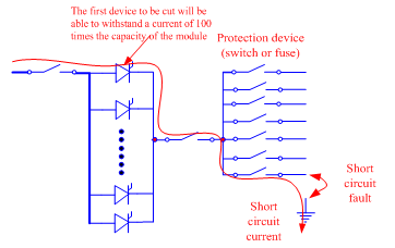
Figure 4. Short circuit fault current schematic
Of course, the manufacturer that disperses the bypass is also well aware of this principle, also provides the corresponding "solution", namely: short circuit condition is only invert to maintain 200 ms, then do not cut bypass, direct shutdown!
Us to explain, 10 times the rated current condition found in the output short circuit conditions, when the inverter does not provide enough current of the breaker failure (usually 3 times rated maintain 200 ms) of the cases, the system will switch to bypass the power supply, with low impedance of the bypass large current short-circuit point to push aside protection device (switch or fuse), it is in the power distribution design must consider, if it is the correct design of power distribution system, distribution of protection design should not produce great protection, namely the downstream of the failure should not lead to upstream of the switching action, the system in the worst case is to switch to bypass, and then use the bypass strong overload capacity made downstream of the protection device, which is the bypass source required by the shock.
Using disperse the bypass system, if forced to switch to bypass, due to the lack of impact resistance and non-synchronous switching, no doubt will cause damage to the device, system outage, so manufacturers design can switch to bypass is prohibited. Can imagine in a complex machine room or factory, as long as there is a branch to have a short circuit fault, the consequence is the whole system hands down! This is not acceptable in practice, but it is an inherent problem that is not solved by dividing the bypass.
3. System reliability analysis
The advantage of dispersion is that the bypass is redundant, the concentrated bypass is considered to be a single point of failure, so let's analyze it.
(1) Analysis from the Angle of device selection
From the Angle of the device, the reliability of a single large power SCR is much higher than the number of small device consisting of a system, focus on the bypass module function is simple, only need to consider the effect of devices and a small amount of peripheral driving circuit, and scattered bypass for distribution within the power module, at the same time affected by modules within a multitude of devices. Have experience in maintenance engineers know, rectifier and inverter circuit failure may be because sparks to causes such as the other part of the circuit fault, that is static bypass the more uncertain risks. If the concentrated bypass is a single failure, the dispersion of the bypass may be called a "multi-point failure".
(2) Analyze from the system capacity Angle
In terms of system capacity, the volume of concentrated bypass is independent of the number of modules configured according to the design of the cabinet. The static by-pass capacity of the distributed bypass is determined by the module capacity, which means that when the module fails, the system will lose the corresponding static bypass capacity. A more extreme example, when two power module rack configuration, if the load rate is about 55%, when a module fault, remaining a module will be at 110% overload condition, the end result is the system off the electricity. The same condition is not a problem for concentrated bypass. Due to the advantages of the device capacity, some manufacturers provide 125% long-term overload capability, which is guaranteed for the reliability of the system.
(3) Analysis of reliability design of concentrated bypass
Focus on the reliability design of the bypass, many mainstream manufacturers also proposed many improve the reliability of the program, such as the redundancy backup scheme of control circuit, communication bus redundancy scheme, power module and the bypass module control decoupling scheme, power module to participate in the bypass control scheme, the solution of each manufacturer have distinguishing feature each, after years of market validation, can greatly improve the system availability, add the bypass module is hot plug design, easy upgrades maintenance and power module.
4. Summed up
Through the above analysis, we hope that we can further understand the difference between the system comprehensive performance and product reliability of the two schemes.
Technical school debate and route selection is normal phenomenon, product development for users, correctly understand the pros and cons of each route is crucial, voice, can avoid the misunderstanding of the concept of marketing. For manufacturers, however, the technical route choice is of great significance, once the route, product development will not be able to midway, subsequent product series will continue, this is why no matter what the industry development, the scattered bypass factory still can't turn to the other side. The most mainstream modular UPS manufacturers, such as Emerson, Eaton, APC, INVT, huawei, etc., are using centralized bypass solutions. Smart customers should understand why.
 Prev
Prev