

When DC bus voltage reduce, VFD reduce the output frequency to ensure the output torque. P27.02=1 active protection, if DC bus voltage is less than P27.03*513VDC, reduce the output f. f/hz=rated Hz*Current DC bus voltage/rated DC bus voltage.
When DC bus voltage reduce and reach the set point, VFD DEC. stop and display A-LvP fault. Until DC bus voltage back to P27.01*motor rated voltage + 20Vdc, reset automatically.P27.00=1 active lower voltage protection.
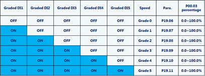
Graded multi-step speed is special for GD20-09, different from multi-step speed function of universal purpose series. Only all lower graded step is ON, the high graded step is avlid.
Active function by P19.37=1, P19.37 can be used together with P05 group input terminal function 60 (Operating lever zero-point position signal) to conduct operating lever zero-point position detection. When the VFD stops, if the operating lever zero-point position signal is enabled (operating lever zeroing), timing starts. At this moment, if operating lever upward or downward running command exits, the VFD does not respond to the command, but if P19.38 is reached, an operating lever fault (StC) will be reported. If the counting time reaches P19.38, it indicates that the zero position is detected uccessfully. The zero position signal is released, and the VFD responds only after being given with the operating lever upward/downward command. In the situation that the zero position signal is not released, if the operating lever upward/downward command is given, an operating lever fault (StC) will be reported. After the VFD stops, the operating lever zeroing starts timing andlasts until P19.38 is reached. Valid running command can be given again only when the zero position is detected successfully.
Generally, it is caused by improper cooperation between the brake and the VFD. The frequency of the VFD has increased, but the brake is opened slowly, resulting in excessive current. This problem is particularly easy to occur in the site where the brake is not controlled by the VFD. The best solution is that the brake is controlled by the VFD.
The main reason is that when the motor is in the power generation state, the motor feeds back energy to the inverter to raise the DC bus voltage to the limit value. It is necessary to check whether the braking resistance or braking unit is damaged or works normally.
Increase the closing delay time of the brake to ensure the continuous output of the VFD during the closing action of the brake.
The full range of medium voltage GD1000/GD2000/GD3000 products can provide two-quadrant or four-quadrant products.
GD5000/3300V products are designed with multi-level power units connected in series. GD3000/3300V adopts a three-level topology design scheme, mainly comparing and replacing ABB ACS1000 series and Siemens GM150 series.


Our site uses cookies to provide you with a better onsite experience. By continuing to browse the site you are agreeing to our use of cookies in accordance with our Cookie Policy.